Diagnose a circuit on a car's brake assist control module )

Thread Starter

cadman777

Joined Dec 23, 2022
47
Hi,
I'm in the process of trying to diagnose a circuit on a car's brake assist control module because it's failed.
The module is no longer available, so I'm resorting to trying to fix it.
However, it's all smd, and has components on it that have no identifying marks on them.
So I was wondering if there is a forum in here that specifically addresses these issues?
Thanks...Chris
 

wayneh

Joined Sep 9, 2010
18,130
Don't worry about it. A moderator may come along and decide it belongs in Technical Repair or some other category, but that's not terribly important. I think most folks here follow all the posts and don't much care where they are pigeon-holed.

Your best bet may be an owners forum for the vehicle(s) that used that particular control module. If you're lucky, others have found a common point of failure and you can leverage that hard-won knowledge. If not, it may be very difficult to make headway beyond careful inspection for obvious problems on the board such as burned components, broken traces, etc.

More details about your vehicle and pictures of the module might help you get more feedback. Good luck.
 
Last edited:

Thread Starter

cadman777

Joined Dec 23, 2022
47
Thanks for your input, Wayne. Yes, I've been to all the forums and they don't really know much at all. I'm operating at a different level than they are since I've been a mechanic since the 70's. Most of the people in those forums are either 'weekend warriors' or ASCE certified techs in their own particular Y/M/M realm. Most of the time they don't get past 'changing parts'. It's bad enough that diagnosing electrical and electronic problems in modern vehicles is a full time speciality. But add to that the need to RE and repair a bad module, and you add one too many levels of complexity to the game. So that's why I'm in here. You guys are the specialists in this stuff.

So, I'm working on a low mileage 1999 Mercedes W202 class sedan. It's got a brake system that's amazing. But the components are no longer available, and the electronics (and other parts, like plastics and rubber) are getting old and need help. This particular part is the BAS module (brake assist). it's part of the ABS/anti-skid/traction system. Anyway, it has 3 systems on it, and one of the circuits on one of the systems is not working right. I already tried fixing it the way you said, but since I can't get a service/diagnostics/schematic manual on it, I'm 'on my own'. Incidentally, recently the radio on this failed. I opened it up to find corrosion in one area. After many searches online, I found the official service manual/schematics/parts list for it. Using a microscope I found the burnt trances and a bad via, and fixed them. While in there I also replaced the SMD's and an IC. Now, that radio (Becker brand) works as good as new. Turned out to be the 'wake-up' circuit. No telling why it went bad. Probably just old. I replaced the main power caps too, just for the sake of PM. So, I've recently been into this sort of thing, which encouraged me to try to diagnose and fix this BAS module.

Regarding the BAS module: I've been trying to RE the PCB in KiCAD to help figure out what might be causing the bad 'net'. But I can't identify a number of the parts. So I need help with that (since I'm no electronics expert). I also need help on understanding how the circuit works. So far I've replaced the only electrolytic capacitor on the board (it showed signs of leakage), the 8-pin IC in the offending circuit, and a tantalum cap that was near the leaking electrolytic cap. When I plugged it into the car and took the voltage measurements, they were basically the same. So I obviously didn't fix the problem. Maybe the electrolytic cap needed replacement, and the other parts didn't?? But whatever is wrong with it still needs to be determined.

There's a lot going on in this little PCB. The offending circuit is the output communications line that's on connector-3, pin 6. It goes to the DLC pin-8. It's supposed to communicate with the ECM, from whence it gets its instructions on the kind of vehicle it is, so the BAS module can select the correct dataset for using in the 'brake assist' computations/operations. The dataset has to do with horsepower, torque, wheel rotation (ABS sensors), speed, etc., which are all vehicle specific. What happens is C3/P6 sends a 1v-2v signal to the ECM, which in turn (don't ask me how) tells the BAS module which PARAMETER to set. That parameter determines the vehicle dataset I just told you about. As it is, C3/P6 is outputting 3.21 volts (supposed to be btw 1-2v). So, I need to get this circuit communicating properly so the ECM can tell the BAS module which dataset to use.

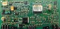
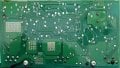
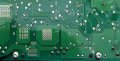
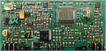
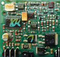
Here are pics of the front and back sides of the module:

1785182071902.jpeg

1785182084965.jpeg
(back side mirrored to match the front side to help prevent confusion when tracing 'nets')

Lower left smd cap and top middle 8-pin IC were replaced. So was the orange cap to the right of the 20 pin IC. The connector pins run along the bottom in 3 groups. The pin of interest is the left most at bottom.

I looked closely at the board through a binocular microscope and didn't find any burnt anything. but there appears to be milky stuff in various places, as you can see, esp. on the back side. But the solder didn't look bad, so I didn't pay it any never mind.

When I first worked up an order for parts (DigiKey), I misjudged the circuit. Since then, been at the RE work for two whole days and not done yet. That single connector pin goes directly to the 8-pin IC, and branches off all around the board from there. So at this point, I'm in over my head and need help b/c I'm not an electronics tech.

Thank you for your interest and willingness to give me some help!
 

Thread Starter

cadman777

Joined Dec 23, 2022
47
btw, what kind of tools/instruments you have at your disposal? scope, logic probe, DMM, ...?
2 channel scope with leads
dmm
wave generator
hot air and temp regulated soldering stations
various and sundry electronics and electrical parts and supplies
only thing is, i'm kind'a rusty on using the scope, since it's been many years since using it
but i do use a scope to get waveforms on vehicles, but it's not quite the same thing
no logic probe (wouldn't know how to use it)
 
things i would normally check first:
1. try to power it up and measure voltages. wider traces indicate pwoer rails.
2. identify all major part numbers and check their datasheets. this is how you get info what voltage is expected and where etc.
3. check if MCU is working. if there is any sign of life (scope or logic probe needed). if MCU is toast, product is usually beyond repair... nless you are ready for some punishment. for example if MCU is damaged but still responds it is great if one can read the code back. then one can try to replace it using part from a donor board or where ever you can source it, and flash it... but i would not hold my breath. there is a good chance that reading back is blocked by blowing internal fuses.
4. probe peripherals and see if they show normal voltages... for example CAN bus is easy to check. and many scopes can decode data too.
5. check for blown fuses, shunts etc. if you have FLIR, check for hot spots.

1785254307236.png
 

Thread Starter

cadman777

Joined Dec 23, 2022
47
There's a blob of solder, where the arrow points, which might be shorting the trace to the ground patch.
Thanks for taking a look at it Alec. I rechecked it under the microscope, and discovered that it's an air bubble captured under the conformal coating. Thankfully, there are no signs of shorting on the board. Thanks for your sharp eye!

Here is an updated front side of the PBC. I connected all the bottom traces.
Notes:
The red lines are the bottom traces.
The red donuts are the vias (front side to back side thru the board).
If there's no line touching a red donut, then it's got no traces on the back side.
If there's a red 'X' in a red donut, then it's connected to a large copper pad (which see on back side of board).
Since I've not detached all the components that have hidden vias and traces under them, I can't tell where the back side vias attach on the front side. I can only guess!
Remember: I mirrored the back side of the board horizontally in the previous pic to make matching-up vias and traces easier. Took me the better part of 6 hours to do this graphic! Thanks to the folks who created "Paint.Net"... fabulous 'paint' program!

1785264111048.png
 

Thread Starter

cadman777

Joined Dec 23, 2022
47
things i would normally check first:
1. try to power it up and measure voltages. wider traces indicate power rails.
2. identify all major part numbers and check their datasheets. this is how you get info what voltage is expected and where etc.
3. check if MCU is working. if there is any sign of life (scope or logic probe needed). if MCU is toast, product is usually beyond repair... unless you are ready for some punishment. for example if MCU is damaged but still responds it is great if one can read the code back. then one can try to replace it using part from a donor board or where ever you can source it, and flash it... but i would not hold my breath. there is a good chance that reading back is blocked by blowing internal fuses.
4. probe peripherals and see if they show normal voltages... for example CAN bus is easy to check. and many scopes can decode data too.
5. check for blown fuses, shunts etc. if you have FLIR, check for hot spots.
Wow! Thanks for this info!
OK, lots to do!

Notes:

1. I have already tested it in the vehicle at the connector pins, but not out of the casing and touching places on the board. I don't know where to begin, since I don't know what's supposed to do what and what is supposed to control what. That's why I came in here, to try to figure out what each component is and then model it up in KiCAD.

2. Still working on it, but some of them are not easy to figure out. I removed all the coating on the tops of all the IC's and got all the numbers off all the IC's and the MCU (removed the bar code sticker too). Tried looking up the MCU and couldn't find anything. That's not saying much b/c I'm not an electronics guy.

3. I hear ya. Not sure how to test it. But I can get the data from Benz for the connector pins, which is a start. I'm working on gathering all that info and 'modeling it up' to create a record of it b/c there's no way I can remember all of this!

Far as donor boards is concerned, I already purchased 4 used modules, and they all have the same problem. The latest one that arrived yesterday. Before buying it I verified with the seller that it was good. But when it arrived it had signs of electrical power arcing inside one of the connector sockets. And THE pin (the one that's got the bad circuit in the original module and also on all the other used ones) was totally missing! So, this may be a 'known defect' for these modules which MB refuses to take responsibility for. Anyway, I don't hold out any hopes for finding a 'known good unit'. If I could, I wouldn't waste time doing this RE work. Instead, I'd just swap-out the parts and be done with it. Same with the rear door control module that's integrated into the window motor. It caused a coms DTC on the interior CANbus. Tracked it down to the CAN-H line on the left rear door module. The connector socket showed signs of overheating, b/c you could see the power line all 'browned-up' in the clear yellow gel. So, something happened there which killed the CAN-H circuit. Anyway, I just disconnected the CAN-H line and let the 'reserve' CAN-L line do the coms work, and it works fine now. A new motor/controller is around $250. Can't afford it. One day I may try to fix this one, not sure, b/c it's gonna be a real DOG to take the PCB out of for testing purposes. Anyway, a new BAS module, IF it exists today (many OEM online sellers list availability until you buy it, then they tell you it's NLA), is listed at over $1000, whereas back in the day they were around 60 bux!

4. Already did all of that. They all check 'good' except the "Diagnostics" line (C3/P6). The module works otherwise, but it's operating on the wrong data ("Parameter 5": for a more powerful engine and heavier vehicle. That's wearing out the brakes too quickly, so I wanna get it fixed.

5. Already did that. Don't have a FLIR, but was 'dreaming about' getting one. Been waiting for 5 years for the resolutions to come up and the prices to go down first.

6. Based on your 'mark-up' in the pic, my next job is to make a representative PCB component block diagram like the Becker service manuals have for their radios. They'll have all the part #'s on it that I can find.

It's gonna take some time to get all this done, after which I'll be back in here with results.

Thanks for the input!
 
Last edited:

Thread Starter

cadman777

Joined Dec 23, 2022
47
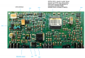
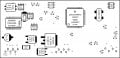
Here's the component block diagram:

1785332016973.jpeg

Notes:
- This is an overlay for Paint.Net (which is where I created it) of the original PBC board front-side that's posted above.
- All unmarked components do not have marks on them.
- The 3 groups of circles at the bottom are the connector pins.
- The offending circuit is on pin-6 all the way to the bottom left.

Back before the internet, I had books I'd use to lookup these components.
But not any more, which means I need sources to find them.
What I usually do is call DigiKey and ask one of their techs to help me find them or their equivalent in their catalog.
But DigiKey isn't always the right source to get these parts from.
Sometimes it's fleaBay, other times it's another mfgr.
If you can tell me where I might find these components, I'll do more searching on my own.

Thanks for the help!
 
Last edited:

Thread Starter

cadman777

Joined Dec 23, 2022
47
Here is a diagram of the circuit that's not testing correctly:

1785333878376.png

Notes:
- It's not connected to that alum.-elec. cap.
- It is connected to the micro smd cap near pin-6.
 

Thread Starter

cadman777

Joined Dec 23, 2022
47
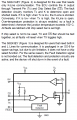
Attached is the spec sheet for the 9241 IC.
The relevant info is as follows:

1785340347284.png

The K & CS are connected to each other on this board by a trace, so this is non-CS and K-line only coms.
Looks like I need to somehow reconnect this module to the vehicle, connect up the scanner, and then probe the TX & K signal at the SO-8 to see what voltages they have. The thing is, in the past with the scanner hooked up, sometimes the K-line was open, and other times it was closed. So, no telling why. Is it possible that the ECM is sending 'mixed (voltage) signals'? Of could the problem be on the board, where some components are not allowing the TX to be the correct voltage (or it's fluctuating) so the 9241 chip malfunctions? The field measurement was this: too high voltage on the K-line at the connector socket pin-6. Am I interpreting the above explanation correctly when thinking that the high voltage means the K-line IS transmitting, but the voltage is wrong, so the ECM can't communicate with the chip? If that's correct, then wouldn't the problem be on the board and not in the ECM (the TX signal)?
 

Attachments

Last edited:
Top