That's how a snubber diode works. When power is removed from an inductive load, the inductance will try to maintain the current that was flowing before power was removed. That will create a voltage across the diode that is the opposite polarity. A snubber diode limits that voltage to about 0.7V.
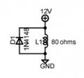
This how to draw your diagram as a schematic.
The resistance given for the inductor allows anyone reading the schematic to calculate the inductor current.
An inductor tries to keep the current flowing when you open the circuit, so it will generate a negative going spike on the positive terminal.
The diode across the coil provides a path for that current, limiting the transient to about -0.7V.
A diode in series will have no effect on that negative spike.
An inductor tries to keep the current flowing when you open the circuit, so it will generate a negative going spike on the positive terminal.
The diode across the coil provides a path for that current, limiting the transient to about -0.7V.
A diode in series will have no effect on that negative spike.
Thank you. I'm trying to understand this the best I can.
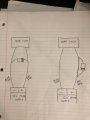
Did you see my crude wiring diagram drawings? Dennis said the drawing on the left would be the correct way to wire in the diode? Do you agree with that?

 Facebook
 Google
 GitHub
 Linkedin