Which current will pass through the relay when the generator and main supply are on?

Thread Starter

johnnewman

Joined Apr 21, 2017
5
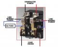
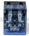
I installed a relay for switching purpose With main supply and Generator. When there is no electricity from main supply relay change its coil to the generator.
I want to know which will be the source of electricity when both the generator and main supply is providing electrical energy to relay.


The person installed a relay is electrician. I was preferring the Changover Switch (manual) for generator, main supply and cut out power (OFF). But he said after starting the generator you have to change the changover switch manually. By relay you only have to ON or OFF the generator and Relay will automatically trip the coil when there is main line power and if there is no main line power by starting generator it trip the coil and power will be of generator.
I am confused that when both main line and generator are giving power to relay what will relay decide, which power it will transfer to home appliances.

I am confused what should I do now, Am I at risk what are the cons or what he did is right?
 

Attachments

Dodgydave

Joined Jun 22, 2012
11,302
Your relay will have a set of Changeover contacts, can you provide a drawing of the wiring for the mains through the contacts,

I assume that the Common terminals of the relay will go to the load, and the changeover will be from the generator and normal mains supply, so when the generator kicks in, it will feed the Coil and changeover from mains to generator.
 

Thread Starter

johnnewman

Joined Apr 21, 2017
5
can
Your relay will have a set of Changeover contacts, can you provide a drawing of the wiring for the mains through the contacts,

I assume that the Common terminals of the relay will go to the load, and the changeover will be from the generator and normal mains supply, so when the generator kicks in, it will feed the Coil and changeover from mains to generator.
can't do that. Someone told me this:


This is a dangerous situation and i hope you dont have the generator and main supply on at the same time. The relays purpose should be to choose the generator if a mains supply is unavailable AND also disconnect the mains before the generator is running. If you have both on you are running 2 risks:

  1. You are endangering power company workers lives. If there is an outage and you have your generator on while the mains is still connected then you will create a backfeed. This energises the section of network you're connected to, and the workers will not know.
  2. If both the generator and mains supply are connected you will more than likely be out of sync with the mains supply when starting the generator. This will result in damage to your generator and any connected equipment. You could also damage nearby connected equipment e.g neighbours and cause fires.
 

Dodgydave

Joined Jun 22, 2012
11,302
Like i said, the Coil will be powered by the generator, and the relay contacts will be changeover between mains and back-up.
 

Dodgydave

Joined Jun 22, 2012
11,302
You need to take the cover off and look at how the coil is wired, i would say it's a changeover relay with the house on the Common terminals, looking at that box the coil maybe across the mains input,?
 

PGB1

Joined Jan 15, 2013
139
Hi,
Perhaps I can help explain in a step-by-step manner.
I have (too) many years' experience designing, building, installing & repairing automatic transfer switches and emergency power installations for industrial and large commercial use. They were mostly non-solid state (old guy that I am...), so I can't help explain yours much if it is solid state without drawings. (Your drawings & links don't show up on my cheap & crabby computer, so I'll explain a typical set-up.)

There is a relay that operates a DPDT contactor (In Single Phase installations). It's job is exactly what a manual transfer switch does, but it is controlled by an electromagnet instead of a person.

The contactor's job is to switch your Load (house) between the Utility Supply & the Generator. The contactor is controlled by a signal from a relay. I understand some house sized units skip the relay and use the contactor only, but I don't have much experience in single phase house units.

For simplicity of explanation, we will skip the relay and pretend the contactor that is doing the switching is controlled directly. It will help to picture a SPDT toggle switch's wiring diagram while you read this. We are working with two poles, but will use one pole for the description, as this is easier to understand.

In order to try to keep this explanation easier to understand, we will call the switching terminal points by these unofficial terms:
The contacts that are normally open, we will call "T-1". This is connected to the Utility Supply.
The contacts that are normally closed, we will call "T-2". This is connected to the Generator Supply.
(Normally Closed means if you take away all power to the coil, those contacts will close.)
The contacts that are able to connect to both, we will call "Load". This is connected to your house's load center.

The "Load" contacts are the center tap on the picture of a SPDT toggle switch you are picturing in your mind. (This isn't how is is shown on diagrams, but it is easier to understand this way when using words, not pictures.)

NOTE- I am skipping all the sensing circuitry that starts the engine and waits for the generator's voltage & frequency to stabilize. There are hundreds of interesting variations available. We are pretending it does not exist in my (possibly futile) attempt to keep this explanation simple.
Also note that on many installations Normally Open and Normally Closed are reversed from what I've written below. It all depends on the switching circuitry. I chose to make N.O. (T-1) the utility for the easiest to understand explanation.

When the Utility Power is available, the contactor's coil is energized by utility power and holds the contactor in Position One. Position One connects the "Load" contacts (your house) to the T-1 contacts (the utility). The poles "T-2" are open. Nothing is powering them.

When the Utility Power fails, the contactor's coil is de-energized and the contactor's springs move the contacts off of T-1 (utility) and onto T-2. (your generator). Your generator is now connected to the feeder going into your house's load center or panelboard.

When Utility Power comes back on line, the contactor's coil is energized by the utility power and switches back to connecting "Load" to "T-1". The signal circuitry senses that the utility power is back and sends a signal to the generator to turn itself off.

Notice that we did not switch the Grounded Circuit Conductor. (Neutral). It is my understanding that in residential, it is common to leave that solidly connected for both generator & utility power. We simply don't bond it to ground in the generator and ground differently. But, your area may require the neutral to be switched as well. Follow you local codes & rules for bonding & grounding and you will be fine.

Some Tips-
Be sure (absolutely sure) to use the generator's weekly self-cycle. If it does not have such a cycle, find out how to start the engine manually. Engines like to be used and have the oil circulated & moisture boiled off. (Plan B is to do a storage routine like is done on lawn mowers & stuff on the engine each time it is used.)

Once in a while, it is good to make the transfer switch actually operate and switch the load. Many generators go for years without the contactor operating. When it is needed (during a power outage), the generator starts, but the contactor is stuck in the 'utility' position. Energizing the switch also allows some current to flow through the alternator's windings. (What we call 'generators' are really alternators.) This is important in small house units (and portables) because some of their exciter circuits (the circuit that initiates the current flow) that are capacitor based. If the capacitor discharges completely, the generator won't have any current output. When you exercise the transfer contactor, put a load on the generator for a minute or two to get the current flowing. This really helps keep the exciter ready for action. (It can be tiny load such as a 60 watt bulb.) Ask the installer or manufacturer for instructions for how to manually force the transfer switching circuitry to operate. You might have a simple disconnect you can open to make the generator's transfer circuitry think the utility has failed.

I hope that my (way too long) explanation helps you understand how your transfer switching works.
Enjoy Today,
Paul
 

AnalogKid

Joined Aug 1, 2013
11,043
Like i said, the Coil will be powered by the generator, and the relay contacts will be changeover between mains and back-up.
If the coil is powered by the generator, you don't get automatic changeover back to the mains when it reappears. That may or may not be a good thing.

ak
 

Dodgydave

Joined Jun 22, 2012
11,302
Hi,
Perhaps I can help explain in a step-by-step manner.
I have (too) many years' experience designing, building, installing & repairing automatic transfer switches and emergency power installations for industrial and large commercial use. They were mostly non-solid state (old guy that I am...), so I can't help explain yours much if it is solid state without drawings. (Your drawings & links don't show up on my cheap & crabby computer, so I'll explain a typical set-up.)

There is a relay that operates a DPDT contactor (In Single Phase installations). It's job is exactly what a manual transfer switch does, but it is controlled by an electromagnet instead of a person.

The contactor's job is to switch your Load (house) between the Utility Supply & the Generator. The contactor is controlled by a signal from a relay. I understand some house sized units skip the relay and use the contactor only, but I don't have much experience in single phase house units.

For simplicity of explanation, we will skip the relay and pretend the contactor that is doing the switching is controlled directly. It will help to picture a SPDT toggle switch's wiring diagram while you read this. We are working with two poles, but will use one pole for the description, as this is easier to understand.

In order to try to keep this explanation easier to understand, we will call the switching terminal points by these unofficial terms:
The contacts that are normally open, we will call "T-1". This is connected to the Utility Supply.
The contacts that are normally closed, we will call "T-2". This is connected to the Generator Supply.
(Normally Closed means if you take away all power to the coil, those contacts will close.)
The contacts that are able to connect to both, we will call "Load". This is connected to your house's load center.

The "Load" contacts are the center tap on the picture of a SPDT toggle switch you are picturing in your mind. (This isn't how is is shown on diagrams, but it is easier to understand this way when using words, not pictures.)

NOTE- I am skipping all the sensing circuitry that starts the engine and waits for the generator's voltage & frequency to stabilize. There are hundreds of interesting variations available. We are pretending it does not exist in my (possibly futile) attempt to keep this explanation simple.
Also note that on many installations Normally Open and Normally Closed are reversed from what I've written below. It all depends on the switching circuitry. I chose to make N.O. (T-1) the utility for the easiest to understand explanation.

When the Utility Power is available, the contactor's coil is energized by utility power and holds the contactor in Position One. Position One connects the "Load" contacts (your house) to the T-1 contacts (the utility). The poles "T-2" are open. Nothing is powering them.

When the Utility Power fails, the contactor's coil is de-energized and the contactor's springs move the contacts off of T-1 (utility) and onto T-2. (your generator). Your generator is now connected to the feeder going into your house's load center or panelboard.

When Utility Power comes back on line, the contactor's coil is energized by the utility power and switches back to connecting "Load" to "T-1". The signal circuitry senses that the utility power is back and sends a signal to the generator to turn itself off.

Notice that we did not switch the Grounded Circuit Conductor. (Neutral). It is my understanding that in residential, it is common to leave that solidly connected for both generator & utility power. We simply don't bond it to ground in the generator and ground differently. But, your area may require the neutral to be switched as well. Follow you local codes & rules for bonding & grounding and you will be fine.

Some Tips-
Be sure (absolutely sure) to use the generator's weekly self-cycle. If it does not have such a cycle, find out how to start the engine manually. Engines like to be used and have the oil circulated & moisture boiled off. (Plan B is to do a storage routine like is done on lawn mowers & stuff on the engine each time it is used.)

Once in a while, it is good to make the transfer switch actually operate and switch the load. Many generators go for years without the contactor operating. When it is needed (during a power outage), the generator starts, but the contactor is stuck in the 'utility' position. Energizing the switch also allows some current to flow through the alternator's windings. (What we call 'generators' are really alternators.) This is important in small house units (and portables) because some of their exciter circuits (the circuit that initiates the current flow) that are capacitor based. If the capacitor discharges completely, the generator won't have any current output. When you exercise the transfer contactor, put a load on the generator for a minute or two to get the current flowing. This really helps keep the exciter ready for action. (It can be tiny load such as a 60 watt bulb.) Ask the installer or manufacturer for instructions for how to manually force the transfer switching circuitry to operate. You might have a simple disconnect you can open to make the generator's transfer circuitry think the utility has failed.

I hope that my (way too long) explanation helps you understand how your transfer switching works.
Enjoy Today,
Paul
This explanation says the Coil is across the Mains supply, and switches the house between mains and generator automatically, a drawing is much easier to understand....
 

PGB1

Joined Jan 15, 2013
139
If the coil is powered by the generator, you don't get automatic changeover back to the mains when it reappears. That may or may not be a good thing.

AnalogKid makes a very good point.

One advantage to having the system not switch back automatically is that you can turn off all of your loads, switch back to utility manually and then turn your loads on one-by-one. This will help protect your equipment. Picture it like this: If your system switches back when your refrigerator and air conditioner are both "on", there may be a momentary voltage drop in your system ( remember the entire neighborhood may also be switching on at the same time as yours is). The drop may damage the equipment. As an added bonus, when the utility supply recovers, the voltage may momentarily climb beyond the normal system voltage. And, if your grounding system is deficient and the neutral is missing when the mains come back on-line, you have a whole new set of equipment damaging troubles.

You can also get a surge when the primary conductors are being spliced in by the utility. In the 'way back' days of the early 1970's I worked as a linesman (until I remembered that it gets really cold in Detroit). When I would do a live primary tap, I could often see the arc and would shudder when I thought about the drop and spike I just delivered to the customers.

I have had recording meters on many systems and would see the drop when the utility is restored and everyone's equipment starts up at the same time. I'd then also see the resultant spike when everything 'catches up'. (My house included.) A surge suppressor should help with the over-shoot, but I don't think it will help with the drop. The people on this forum would know way more than I ever will about protecting against the voltage drop and surge.

Unless you really need automatic changeover (like if you are gone in winter and want the furnace on during outages or have someone at home who needs medical equipment powered 24/7), a manual transfer switch puts you in total control. There are expensive work-arounds, mostly involving rectifier and inverter circuitry, sometimes with storage batteries involved. (Kind of like a giant UPS.)

Paul
 

PGB1

Joined Jan 15, 2013
139
This explanation says the Coil is across the Mains supply, and switches the house between mains and generator automatically, a drawing is much easier to understand....
I apologize Dave that for some reason I can't add a drawing to this thread. I did post a question of my own and the drawing was allowed. Beats Me!

If you do an internet search for a schematic of an automatic transfer switch, you'll find schematics and wiring diagrams. Eaton dot com is good about having both schematics & diagrams. They still make non-electronic types.

I think I way over-explained. I guess I am a way better doer than explainer.

Picture it like this-
Notes:
A contactor moves contact points by an electromagnet that is energized by a coil. It returns by spring(s).
In this example, "Load" is your house. Line 1 is Utility. Line 2 is Generator.

Operation Simplified:
A Double Throw contactor has Utility on Line 1 terminals and Generator on Line 2 terminals. Your house is on the center (common) terminals.
The contactor is electro-magnetically held as Load-Connected-To-Line 1 by the coil. When the utility fails, the coil is de-energized.
The contactor's springs move the position of the Load contacts to connect to Line 2.
Your generator is now connected to the house system & the utility is isolated.
When utility is restored, the coil is re-energized and the contactor's Load terminals are drawn electromagnetically back to Line 1

In real life, it is a bit more complicated.
I hope this clarifies. I'll try again later to see if I can post a simple sketch of the circuitry.

Paul
 

PGB1

Joined Jan 15, 2013
139
One thing I forgot to mention that you should consider, John is your insurance company's reaction to your set up.

In the US, NFPA 70 articles 90.7 and 100.3, et. al., require approval or listing of electrical equipment. (Quoting article numbers from memory, I may have missed on the numbers.)
Generally this means the equipment is to be listed by an approved testing agency. (Examples are UL, ETL, CSA).
If all the individual components are listed, it may or may not be allowed it to exist in your home as an "assembly". I have had site-built systems be rejected by the client's insurance company until I submitted the assembly for testing. I have also had the requirement waived.

And, all electrical installations must be inspected & approved by the Authority Having Jurisdiction. (AHJ)

Why This Is Very Important-
You want to be sure you have a safe installation in your home. And...
If you ever have a fire, or if a utility worker is injured or killed by a back-feed, your insurance company may decide not to honor your claim.


What To Do-
A very important task is to make certain that the installing contractor obtains a permit from the local jurisdiction and has the installation inspected and approved by the AHJ. (Don't apply for a homeowner's permit. Have the installing contractor get the permit in her or his company's name. He or she has liability insurance. You want your insurance company completely out of the picture.)

In the event of an expense related to a failure of the equipment, this inspection 'green tag' will allow your insurance company to shift the burden-of-payment from themselves to the local jurisdiction who approved the installation (and maybe the system builder/installer).

I hate to be all Mister Grouchy Pants about this, but experience has let me learn from others' mistakes.
Paul
 
Last edited:
Top