 Facebook
 Google
 GitHub
 Linkedin
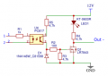
Can I connect a momentary button between 12V and Pin3 to turn on the load?
(Pin1 and Pin2 may be used in the future to interface a microcontroller to control the load through PWM with a 3.3V signal)
(Pin1 and Pin2 may be used in the future to interface a microcontroller to control the load through PWM with a 3.3V signal)
Attachments
-
 15.6 KB Views: 43


")


