Wheatstone Bridge with INA 129 NOT WORKING, HELP NEEDED

Thread Starter

Reyleight

Joined Dec 13, 2016
25


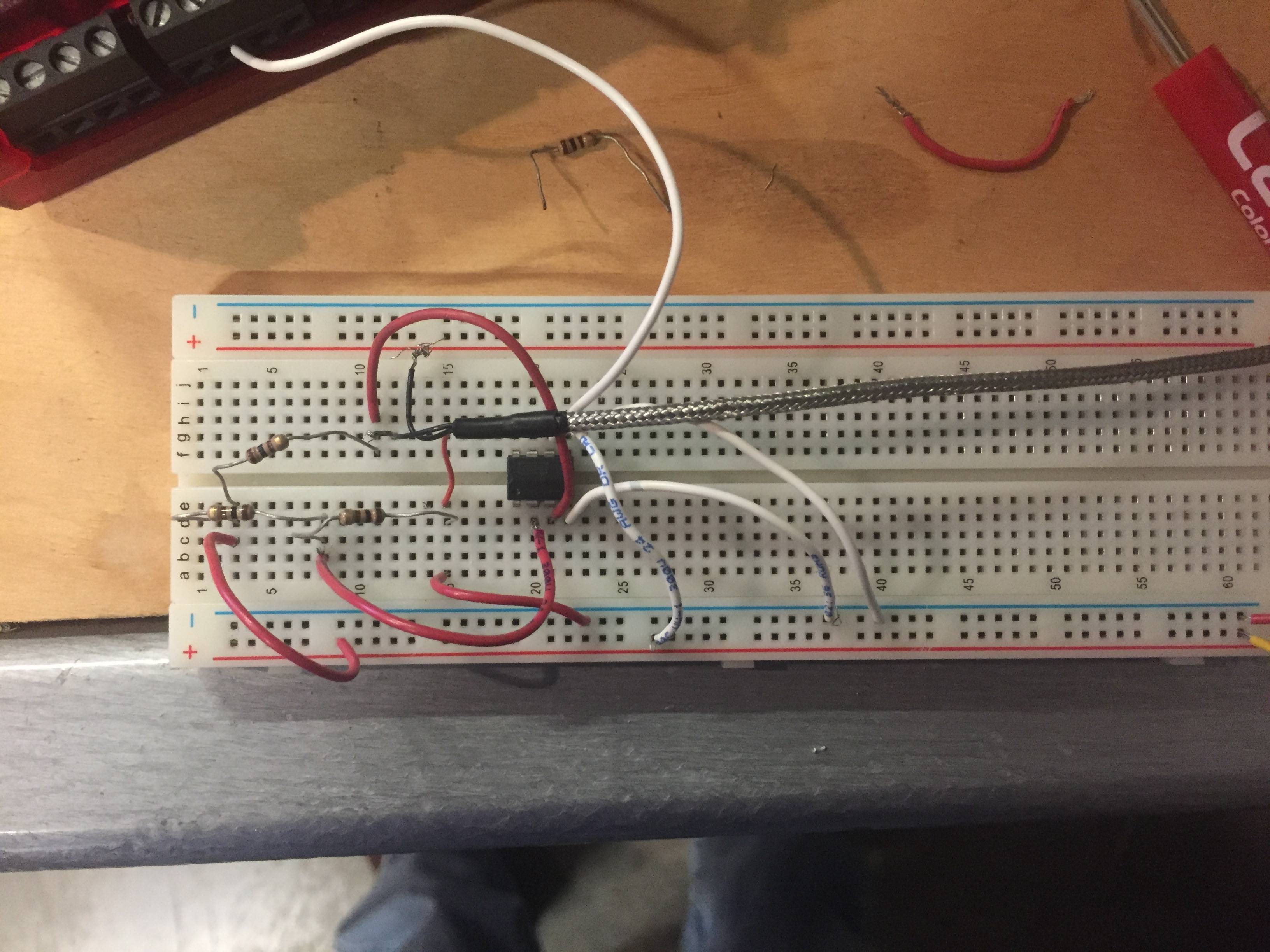
Attached is a picture of the circuit I have built. It is a Wheatstone bridge built with 3 100 Ohm resistors, and with a variable resistance in the form of a PT100 RTD. I then have it connected to an Instrumentation Amplifier 129. http://www.ti.com/lit/ds/symlink/ina128.pdf This is the datasheet.

I bought it here http://www.ti.com/product/INA129 and this is where it says a minimum of 4.5 voltage source.

I connected My V+ in and V- in in the correct places, as well as the 12 V power supply I have running through it. I put the reference to the ground on the breadboard, and V+ to the power, and V- to the ground as well. I did not use the R_gain, so at the moment I only have a gain of 1. Eventually I'd like a gain of 2, also the labjack U3 has a max input voltage of 2.4 V.

The white wire coming out at the top of the picture is my voltage out going to a port in the labjack in which it would show the voltage coming out, and in the far right you can see that I had my ground/voltage source connected. I am using an external voltage source of 12 V, to clarify labjack U3 also has a voltage source and ground. However it only outputs a max of 5 V and that's about the bare minimum the INA 129 needs to run.

I am not getting the readings I should be getting, for example the resistance of that RTD at the time was 110.5 Ohms, meaning my voltage output should have been about .299 volts. However my voltage was just fluctuating randomly, from 1-2.4 volts. Does anyone have any advice? Have I set up my circuit incorrectly, or is my INA 129 perhaps faulty? If there is a better In-amp option than the 129 then I would appreciate it if you could let me know. I'll have to set up 8 of these for 8 RTDs in about a week or two.

TLDR: Wheatstone Bridge with INA 129 is not getting the proper voltage output with the RTD and a voltage source of 12 V. What is wrong with my circuit, and how can I improve it? ANY suggestions are welcome.

Thank you for your time.

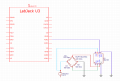
EDIT: Here is a schematic I just made. I wasn't sure how to draw the power supply, but it is drawing 12 V from a DC power supply, and all of the grounds are connected to the ground on that power supply.


Attachments

Sensacell

Joined Jun 19, 2012
3,783
You are using the opamp with a single supply, and you have made the negative supply rail your reference.
The INA129 is not a rail-to-rail amplifier, the inputs and outputs cannot go to the negative supply rail.

Look at the data sheet:

Common Mode Voltage Range- minimum is 2 volts lower than the V+, and 2 volts higher than V-
Output Voltage Range- not closer than 1.4 V to either supply rail.

You need to add a negative power supply voltage to the circuit, then the GND reference and inputs can be in the valid range.
 

crutschow

Joined Mar 14, 2008
38,484
This not a rail-rail amp as Sensacell noted so you need a dual supply, or go to a single supply type instrumentation amp.

I also see a likely serious problem with your RTD sensor.
With 12V across the bridge it will be dissipating about 6²/100 = 0.36W :eek: and that will generate a lot of self heating. It will be very hot to the touch.
Normally you want to keep the self heating to no more than a few mW.
This means keeping current through the sensor to no more than a few mA, so the bridge voltage should be less than a volt.
This reduces the bridge sensitivity, of course, so you will need to operate at a higher amplifier gain.

One way to further reduce bridge power and self heating is to only power the bridge for the few ms it takes to make a reading.
 

Thread Starter

Reyleight

Joined Dec 13, 2016
25
This not a rail-rail amp as Sensacell noted so you need a dual supply, or go to a single supply type instrumentation amp.

I also see a likely serious problem with your RTD sensor.
With 12V across the bridge it will be dissipating about 6²/100 = 0.36W :eek: and that will generate a lot of self heating. It will be very hot to the touch.
Normally you want to keep the self heating to no more than a few mW.
This means keeping current through the sensor to no more than a few mA, so the bridge voltage should be less than a volt.
This reduces the bridge sensitivity, of course, so you will need to operate at a higher amplifier gain.

One way to further reduce bridge power and self heating is to only power the bridge for the few ms it takes to make a reading.
Is there any inamp you recommend me to use? And it's no problem to lower the power supply as long as it's enough to be in range of whatever inamp I end up using.

Edit:
This is the first one I found: http://www.ti.com/product/INA122 , http://www.digikey.com/product-detail/en/texas-instruments/INA122PA/INA122PA-ND/300981
It's a single supply type, and its minimum is 2.2 V. Also due to the minimum gain being 5 I have to keep my power supply at about 5 V so the max readings I'm going to take (at 100 deg C) don't go over my 2.4 V limit on the U3. Just to make sure, if I don't set any resistors for the gain, it does keep my minimum gain?
 
Last edited:

Thread Starter

Reyleight

Joined Dec 13, 2016
25
You are using the opamp with a single supply, and you have made the negative supply rail your reference.
The INA129 is not a rail-to-rail amplifier, the inputs and outputs cannot go to the negative supply rail.

Look at the data sheet:

Common Mode Voltage Range- minimum is 2 volts lower than the V+, and 2 volts higher than V-
Output Voltage Range- not closer than 1.4 V to either supply rail.

You need to add a negative power supply voltage to the circuit, then the GND reference and inputs can be in the valid range.[/QUOTE

Ah...that would explain it. Suggestions for an inamp that's single power supply?

I found this one http://www.ti.com/product/INA122 and I explained in the other reply.
 

Thread Starter

Reyleight

Joined Dec 13, 2016
25
Is there any inamp you recommend me to use? And it's no problem to lower the power supply as long as it's enough to be in range of whatever inamp I end up using.

Edit:
This is the first one I found: http://www.ti.com/product/INA122 , http://www.digikey.com/product-detail/en/texas-instruments/INA122PA/INA122PA-ND/300981
It's a single supply type, and its minimum is 2.2 V. Also due to the minimum gain being 5 I have to keep my power supply at about 5 V so the max readings I'm going to take (at 100 deg C) don't go over my 2.4 V limit on the U3. Just to make sure, if I don't set any resistors for the gain, it does keep my minimum gain?
Or this one: http://www.ti.com/lit/ds/symlink/ina121.pdf

Minimum 4.5 V single supply, and has a minimum gain of 1 so I can change the output as much as I want?
 
Last edited:

crutschow

Joined Mar 14, 2008
38,484
............
This is the first one I found: http://www.ti.com/product/INA122 , http://www.digikey.com/product-detail/en/texas-instruments/INA122PA/INA122PA-ND/300981
It's a single supply type, and its minimum is 2.2 V. Also due to the minimum gain being 5 I have to keep my power supply at about 5 V so the max readings I'm going to take (at 100 deg C) don't go over my 2.4 V limit on the U3. Just to make sure, if I don't set any resistors for the gain, it does keep my minimum gain?
That amp should work.

But, as I previously noted, you can still get significant self heating of the PT100 sensor.
At 5V bridge voltage, the PT100 dissipation is 62.5mV.
In free air, the sensor temperature rise is about 0.2°C/mw, giving an increase of 62.5 * 0.2 = 12.5°C.
So, unless the sensor is immersed in a liquid, that's not acceptable.
You will likely need to reduce the voltage on the bridge to a volt or less, well below the amp operating voltage.
This can be done with a voltage regulator (which the bridge should have anyway for best accuracy).

What are you measuring the temperature of, and what temperature measurement accuracy do you need?
 

Thread Starter

Reyleight

Joined Dec 13, 2016
25
That amp should work.

But, as I previously noted, you can still get significant self heating of the PT100 sensor.
At 5V bridge voltage, the PT100 dissipation is 62.5mV.
In free air, the sensor temperature rise is about 0.2°C/mw, giving an increase of 62.5 * 0.2 = 12.5°C.
So, unless the sensor is immersed in a liquid, that's not acceptable.
You will likely need to reduce the voltage on the bridge to a volt or less, well below the amp operating voltage.
This can be done with a voltage regulator (which the bridge should have anyway for best accuracy).

What are you measuring the temperature of, and what temperature measurement accuracy do you need?
I am measuring the temperature of an air conditioning unit at various spots of the coils inlets/outlets. I won't be measuring anything above 100 degrees C and as long as I get within a degree or so of the actual then I'd be fine.

What dissipation is acceptable? For example I could lower it to 2.5 V source or 3 V source since 2.5 V is too close to the required voltage for the amp. If not how do I incorporate a voltage regulator into my system?

3V source is an increase of 4.5 deg C.
 

crutschow

Joined Mar 14, 2008
38,484
I am measuring the temperature of an air conditioning unit at various spots of the coils inlets/outlets. I won't be measuring anything above 100 degrees C and as long as I get within a degree or so of the actual then I'd be fine.

What dissipation is acceptable? For example I could lower it to 2.5 V source or 3 V source since 2.5 V is too close to the required voltage for the amp. If not how do I incorporate a voltage regulator into my system?
Do you know Ohm's law?
The power dissipated in the sensor is 0.5V²/100 where V is the bridge voltage.
To keep the self heating below 1°C, the maximum dissipation should be 1°C/0.2mw/°C = 5mw.
This means the maximum sensor voltage should be √(.005*100) = 0.7V, so the maximum bridge voltage should be 1.4V.
The minimum output of an LM317 regulator with the ADJ connected to ground is 1.25V so that would work for your bridge voltage.
That will give a bridge output of ≅1.216mV/°C change in temperature.
Your amp thus would need a gain of 1973 to give an output of 2.4V at 100°C.

But another question is, why are you using PT100 sensors if you need no more than a degree or two accuracy?
An IC temperature sensor such as the AD590 requires only two wires and outputs a calibrated signal of 1μA/°K.
You convert the current to a voltage by having a resistor in series with the sensor.
For example, 10kΩ in series will give 10mV/°K voltage output at the receiver end.

Another common IC sensor is the LM35, which gives an output of 10mV°C.
It has the advantage of no offset for a Celsius scale, thus 0°C =0V and 100°C = 1V output.
But it does require 3 wires to the sensor.

Note that, to minimize noise pickup, twisted shielded wire should be used from the receiver to the sensor.
Some low-pass filtering may also be required to suppress signal noise, such as from the power line.
 

Thread Starter

Reyleight

Joined Dec 13, 2016
25
Do you know Ohm's law?
The power dissipated in the sensor is 0.5V²/100 where V is the bridge voltage.
To keep the self heating below 1°C, the maximum dissipation should be 1°C/0.2mw/°C = 5mw.
This means the maximum sensor voltage should be √(.005*100) = 0.7V, so the maximum bridge voltage should be 1.4V.
The minimum output of an LM317 regulator with the ADJ connected to ground is 1.25V so that would work for your bridge voltage.
That will give a bridge output of ≅1.216mV/°C change in temperature.
Your amp thus would need a gain of 1973 to give an output of 2.4V at 100°C.

But another question is, why are you using PT100 sensors if you need no more than a degree or two accuracy?
An IC temperature sensor such as the AD590 requires only two wires and outputs a calibrated signal of 1μA/°K.
You convert the current to a voltage by having a resistor in series with the sensor.
For example, 10kΩ in series will give 10mV/°K voltage output at the receiver end.

Another common IC sensor is the LM35, which gives an output of 10mV°C.
It has the advantage of no offset for a Celsius scale, thus 0°C =0V and 100°C = 1V output.
But it does require 3 wires to the sensor.

Note that, to minimize noise pickup, twisted shielded wire should be used from the receiver to the sensor.
Some low-pass filtering may also be required to suppress signal noise, such as from the power line.
Well I'm using PT100s because that's what was already set up on the AC unit. So I just have to work with what we have. Ideally I want the most accurate measurement I can get, but if it is a degree off then it won't be a big deal for my uses.

EDIT:

So let me get this straight.

In this case I would have a 5 Volt source, and I would have my voltage source connected to the LMT 317, and output 1.25 V into my wheatstone bridge. Which is under the max of 1.4 volts I could have going in to be uder 1 deg C.

From there I should connect everything else as I did in my schematic, and if I want my max voltage to be 2.4 V @ 100 deg C (the limit of labjack U3) then I would set a gain of 1973?

To clarify my INA 122 would still be connected to my 5 V voltage source because it requires a minimum of 2.2 V to function?
 
Last edited:

crutschow

Joined Mar 14, 2008
38,484
Where would I put the LM317 regulator? After the V+in and -in of the Wheatstone bridge?
It can be between the +12V and the plus side of the bridge.
The minus side of the bridge goes to ground.

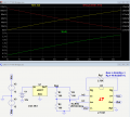
Here's an LTspice simulation of that:
I didn't have a model for your amp so I used one I had, which required the dual supplies.
The LM317 gives a regulated output of 1.25V to the bridge.
The simulated bridge output for a PT100 resistance change of 100Ω (0°C) to 138.5Ω (100°C) gives a bridge output of 0V to about 100mV.
This is amplified by an amp gain of about 24 to give your desired 0V to 2.4V output.
The maximum PT100 dissipation (top red trace) is about 4mW, giving an increase in temperature of about 0.8°C.

Note that such a low signal will be subject to noise and power line pickup.
Shielding of the line is very important.
You may also need to low-pass filter the signal to suppress the noise.
If you need more signal to get a better signal-to-noise ratio, you will have to momentarily pulse the bridge with a higher voltage during the measurement.
Do you have a control processor that can generate a pulse to do that?

upload_2017-2-21_13-49-31.png
 

Attachments

Thread Starter

Reyleight

Joined Dec 13, 2016
25
It can be between the +12V and the plus side of the bridge.
The minus side of the bridge goes to ground.

Here's an LTspice simulation of that:
I didn't have a model for your amp so I used one I had, which required the dual supplies.
The LM317 gives a regulated output of 1.25V to the bridge.
The simulated bridge output for a PT100 resistance change of 100Ω (0°C) to 138.5Ω (100°C) gives a bridge output of 0V to about 100mV.
This is amplified by an amp gain of about 24 to give your desired 0V to 2.4V output.
The maximum PT100 dissipation (top red trace) is about 4mW, giving an increase in temperature of about 0.8°C.

Note that such a low signal will be subject to noise and power line pickup.
Shielding of the line is very important.
You may also need to low-pass filter the signal to suppress the noise.
If you need more signal to get a better signal-to-noise ratio, you will have to momentarily pulse the bridge with a higher voltage during the measurement.
Do you have a control processor that can generate a pulse to do that?

View attachment 121034
OH! Thank you, so in my case with the INA 122, everything is set up the same way besides the V- which goes to my ground, correct? And my gain would still be the same as well, because the max voltage across my bridge would still be .1 V at 100 deg C (138.5 Ohms)?

I do not have a control processor, also I was thinking of having a live signal to show the temperature increasing(or decreasing) as the AC unit is turned on. I'm also already working with Java to create a GUI to read all of the channels from labjack, and within a month I'll have to order a custom board for this to make a more permanent setup for the RTDs once I get it to work.

I do believe my RTD wires are shielded properly. Would power lines produce enough noise to skew my results more than a degree? I'm thinking at this point it would just be a matter of testing it. Or would a low pass filter suffice? I am unsure as I've never used one before.

Also to convert my voltage to temperature should I use y=(x*24)/.024 ? For example if it gives me temperatures within 1 degree near 0 and 100 deg C, but in the middle such as at 50 deg C I get an output of 55.3 deg C instead. Should I just take more data points of the voltages and temperatures and create a better line?
 
Last edited:

Thread Starter

Reyleight

Joined Dec 13, 2016
25
It can be between the +12V and the plus side of the bridge.
The minus side of the bridge goes to ground.

Here's an LTspice simulation of that:
I didn't have a model for your amp so I used one I had, which required the dual supplies.
The LM317 gives a regulated output of 1.25V to the bridge.
The simulated bridge output for a PT100 resistance change of 100Ω (0°C) to 138.5Ω (100°C) gives a bridge output of 0V to about 100mV.
This is amplified by an amp gain of about 24 to give your desired 0V to 2.4V output.
The maximum PT100 dissipation (top red trace) is about 4mW, giving an increase in temperature of about 0.8°C.

Note that such a low signal will be subject to noise and power line pickup.
Shielding of the line is very important.
You may also need to low-pass filter the signal to suppress the noise.
If you need more signal to get a better signal-to-noise ratio, you will have to momentarily pulse the bridge with a higher voltage during the measurement.
Do you have a control processor that can generate a pulse to do that?

View attachment 121034

http://www.digikey.com/product-detail/en/texas-instruments/LM317T/LM317T-ND/3701346

Is this the LM317 you're referring to? I found a few others but they had 1.2 V as their minimum input voltage.
 

crutschow

Joined Mar 14, 2008
38,484
so in my case with the INA 122, everything is set up the same way besides the V- which goes to my ground, correct? And my gain would still be the same as well, because the max voltage across my bridge would still be .1 V at 100 deg C (138.5 Ohms)?
Yes the connection and required gain are as you state.
The gain is approximate.
You would need to calculate that for the actual sensor you have.
Would power lines produce enough noise to skew my results more than a degree? I'm thinking at this point it would just be a matter of testing it. Or would a low pass filter suffice?
How much noise you have and whether it would need a LP filter would best be determined by testing, as you state.
Should I just take more data points of the voltages and temperatures and create a better line?
How many data points you need is determined by the accuracy required.
Are you planning on doing any calibration of the system?
Certainly it wouldn't be to difficult to test at 0°C (ice water) and 100°C (boiling water, depending upon altitude).
 

Thread Starter

Reyleight

Joined Dec 13, 2016
25
Yes, I would like to calibrate the system.
I have already tested it at boiling water but I got approximately 137 Ohms for boiling water, my altitude is only 463 ft.
I'll be testing it in ice water as soon as I can, and I will also take at least another 8 data points at different temperatures of water and use that to approximate my scaling equation.

This is the correct LM317 right? http://www.digikey.com/product-detail/en/texas-instruments/LM317T/LM317T-ND/3701346

I found a few others that were similar but didn't have a minimum output of 1.25 V.
 

crutschow

Joined Mar 14, 2008
38,484
I'll be testing it in ice water as soon as I can, and I will also take at least another 8 data points at different temperatures of water and use that to approximate my scaling equation.
For best results you should calibrate it in the bridge with the amp and voltage regulator so you compensate for all errors.
This is the correct LM317 right? http://www.digikey.com/product-detail/en/texas-instruments/LM317T/LM317T-ND/3701346

I found a few others that were similar but didn't have a minimum output of 1.25 V.
Yes, that's the correct device.
It also comes in smaller packages, which are fine, since it will dissipate very little power in your application.

All 317 regulators go to 1.25V minimum voltage.
 

Thread Starter

Reyleight

Joined Dec 13, 2016
25
For best results you should calibrate it in the bridge with the amp and voltage regulator so you compensate for all errors.
Yes, that's the correct device.
It also comes in smaller packages, which are fine, since it will dissipate very little power in your application.

All 317 regulators go to 1.25V minimum voltage.
Alright, well I just ordered the amps and the regulators, I should be able to begin testing in a few days and I'll update then on my results! Thank you for your help!
 

crutschow

Joined Mar 14, 2008
38,484
I did some further thought on your problem and realized that you could actually get a higher output voltage from the bridge if you went to a unsymmetrical bridge with a 12V supply, by using much larger resistors in the top of the bridge to reduce the current and dissipation in the PT100 sensor.

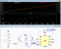
The simulation of that is below.
I used 2kΩ resistors in the top of the bridge to keep the PT100 dissipation about the same as with the low voltage bridge with 100Ω resistors.
And, due to the higher impedance load for the PT100, it's output is now about 200mV at a simulated 100°C, double of the low voltage bridge.
This improves the signal to noise ratio and requires a lower amp gain for the same 2.4V output.

So, if you decide to use this latest circuit, I apologize that you bought some regulators you didn't need. :oops:

upload_2017-2-22_0-56-40.png
 

Attachments

Top