Wheatstone Bridge-MCP6N11 Testing

Thread Starter

ayractgc

Joined Feb 3, 2018
52
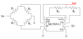
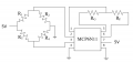
I want to test wheatstone bridge circuit wtih an instrumental amplifier MCP6N11.First of all, i tested all of the system totally but it didn't work so ı tested wheatstone bridge
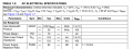
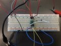
and it worked.But I want to test MCP6N11.I give a signal from the pin 2 and pin 3 , 1khz and 1Vpp. I connected 2 resistance 2k and 1k as a gain resistance between pin 5 and pin6 .ı connected pin 1 between these pins.ı connected power supply to pin 7 and pin 4. Finally ı connected pin8 to the ground so it connected to the pin4.I give 5 V power to the amplifier.But i didn't take any result from the ossiloscope.Should ı add a resistor or something?
 

Attachments

ericgibbs

Joined Jan 29, 2010
21,408
hi ay,
Check pin #5 Vref on the datasheet.
E

EDIT:
You have pin #8 connected to 0V, so the Amp is in the CAL mode.??
 

Attachments

Last edited:

Thread Starter

ayractgc

Joined Feb 3, 2018
52
thanks for your answer,
ı forgot to write that ı connected pin8 to the ground but ı changed it and ı connected it to the power supply 5V.But still not working
For pin5,
this is the block diagram so ı connected it like here.
 

Attachments

MrChips

Joined Oct 2, 2009
34,671
If you apply a 1kHz signal at the bridge, you get a difference signal at the arms of the bridge. This gets amplified by the MCP6N11 instrumentation amplifier and output appears on pin-6.

Make sure pin-8 EN/CAL is connected to VDD, pin-7.
 

Thread Starter

ayractgc

Joined Feb 3, 2018
52
If you apply a 1kHz signal at the bridge, you get a difference signal at the arms of the bridge. This gets amplified by the MCP6N11 instrumentation amplifier and output appears on pin-6.

Make sure pin-8 EN/CAL is connected to VDD, pin-7.
Can ı test it singly with 1khz 1Vpp input pins?
Pin8 is connected to the pin7 ,picture is wrong ı am sorry.
 

ericgibbs

Joined Jan 29, 2010
21,408
hi ay,
No do not add that 10K, its referring to the 0.9K output impedance of the amp.
It is important that the Vref is sourced from a low impedance drive ie: OPA output or a simple 2.5V zener would be OK for testing your project.
Lets know it goes.
E
 

Thread Starter

ayractgc

Joined Feb 3, 2018
52
hi ay,
No do not add that 10K, its referring to the 0.9K output impedance of the amp.
It is important that the Vref is sourced from a low impedance drive ie: OPA output or a simple 2.5V zener would be OK for testing your project.
Lets know it goes.
E
Still it is not working.I connected Pin8 to the Vdd
and I connected Vref Vdd/2.
But it didn't work :/
 

Attachments

ericgibbs

Joined Jan 29, 2010
21,408
hi a,
I will look over your images, see what I can find.
E

EDIT:
The images look OK, except pin #5 cannot be seen clearly connected to the 10k?
What voltage do you measure from pins #3 and #4 relative to 0V.?
 

Attachments

Last edited:

Thread Starter

ayractgc

Joined Feb 3, 2018
52
hi a,
I will look over your images, see what I can find.
E
I have a 100 V/V gain amplifier.But I set up my circuit 2V/V gain.In the data sheet it is written that Gmin is 100V/V for gain 100 amplifier.Is it problem about that?Should ı use 100 gain for this circuit?

Untitled_ayractgc.jpg
 

Thread Starter

ayractgc

Joined Feb 3, 2018
52
hi a,
I will look over your images, see what I can find.
E

EDIT:
The images look OK, except pin #5 cannot be seen clearly connected to the 10k?
What voltage do you measure from pins #3 and #4 relative to 0V.?
1k is connected to the Pin5 and 2k is connected to the 2k ohm
 

ericgibbs

Joined Jan 29, 2010
21,408
hi,
A marked up circuit diagram, showing the component values and the way pins 3 & 4 are connected, would be helpful.
These two images show the d/s circuits.
E
 

Attachments

Top