Facebook
 Google
 GitHub
 Linkedin

Elerion:
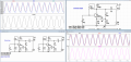
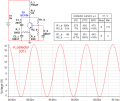
And it works with 100 kohm base resistor, 24 ohm emitter resistor and 12 ohm feedback resistor.
A little distorted on the bottom, but pretty decent.
And obviously (?) it works if feeding a larger resistor load.
Of course, with larger resistor load (without external load current) it works just fine, because it calculated for R_l=1kOhm, and normalized resistance of dissipation in oscillator has similar value.
Elerion:
Where did you take all those rules from? From experience?
These rules are result of multiple oscillator simulations data analyzing.
Elerion:
This circuit is not exactly the typical colpitts oscillator seen in manuals.
It should be so, because I was trying to resolve several problems together:
1. Define optimal inductive (capacitive) reactance of tank components.
2. Define optimal values ratio of capacitors in tank.
3. Increase efficiency, by value of emitter resistor decreasing.
4. Create distinct path for distortion control.
Elerion:
Also, this circuit it doesn't use a voltage divider at the transistor base, just a single "pull-up"
resistor.
In this circuit may be used voltage divider (see attachement).
Elerion:
Did you explore these alternatives?
When I asked "did you explore these alternatives?", I meant common collector and common emitter versions of
colpitts oscillator.
Explore for what? What are problems, need to be solved?
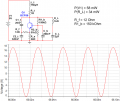
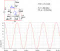
And it works with 100 kohm base resistor, 24 ohm emitter resistor and 12 ohm feedback resistor.
A little distorted on the bottom, but pretty decent.
And obviously (?) it works if feeding a larger resistor load.
Of course, with larger resistor load (without external load current) it works just fine, because it calculated for R_l=1kOhm, and normalized resistance of dissipation in oscillator has similar value.
Elerion:
Where did you take all those rules from? From experience?
These rules are result of multiple oscillator simulations data analyzing.
Elerion:
This circuit is not exactly the typical colpitts oscillator seen in manuals.
It should be so, because I was trying to resolve several problems together:
1. Define optimal inductive (capacitive) reactance of tank components.
2. Define optimal values ratio of capacitors in tank.
3. Increase efficiency, by value of emitter resistor decreasing.
4. Create distinct path for distortion control.
Elerion:
Also, this circuit it doesn't use a voltage divider at the transistor base, just a single "pull-up"
resistor.
In this circuit may be used voltage divider (see attachement).
Elerion:
Did you explore these alternatives?
When I asked "did you explore these alternatives?", I meant common collector and common emitter versions of
colpitts oscillator.
Explore for what? What are problems, need to be solved?
Last edited: