Facebook
 Google
 GitHub
 Linkedin
Senario:
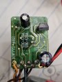
A functioning toy locomotive powered by 3(AA) batteries producing 4.5VDC to this IC board.
Topic:
Can anyone explain to me how I'm receiving a short indicator from my multimeter between the bottom of the 164 resistor coming off the base of Q3 and the bottom of the 104 resistor? (Upper left hand corner of photo.)
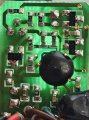
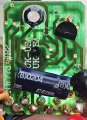
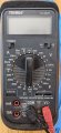
I took a photo of my multimeter and the two resistos with back lighting. One photo of the IC board is from the SMD side, and the other is from the THT side.
On either side, I see no leads running between the two resistors. But when I check with my multimeter it indicates a short, but when I run a voltage check, I get 2.3VDC at the bottom of 164 leading to Q3, and 4VDC at the bottom of 104.
How can one have a short between two different components and two different voltage levels as well?
I know the answer is simple, but I can't explain my reading and my observations.
Thank you.
A functioning toy locomotive powered by 3(AA) batteries producing 4.5VDC to this IC board.
Topic:
Can anyone explain to me how I'm receiving a short indicator from my multimeter between the bottom of the 164 resistor coming off the base of Q3 and the bottom of the 104 resistor? (Upper left hand corner of photo.)
I took a photo of my multimeter and the two resistos with back lighting. One photo of the IC board is from the SMD side, and the other is from the THT side.
On either side, I see no leads running between the two resistors. But when I check with my multimeter it indicates a short, but when I run a voltage check, I get 2.3VDC at the bottom of 164 leading to Q3, and 4VDC at the bottom of 104.
How can one have a short between two different components and two different voltage levels as well?
I know the answer is simple, but I can't explain my reading and my observations.
Thank you.
Attachments
-
 2 MB Views: 16
 -
 1.7 MB Views: 17
 -
 2.7 MB Views: 17