What would make a shaft vibrate at a frequency twice its RPM?

Thread Starter

strantor

Joined Oct 3, 2010
6,798
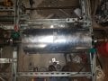
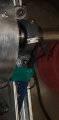
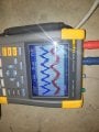
I'm trying to balance a rotatating drum on a prototype machine I'm building, and I have never done any dynamic balancing before. Most people use accelerometers for this but I don't have any so I'm using Piezo flex sensors with little overhung weights (https://www.sparkfun.com/products/9197). I have them held in my scope probes and just taped the probes onto the bearings on either side of the shaft. I'm running the motor (4 pole) on 50Hz so I expect to see a 25Hz waveform on both ends corresponding to to the imbalance. I do get the expected 25Hz on one end but on the other I get 50Hz.

Is this due to the small weight on the piezo sensor vibrating at a multiple of the vibration frequency seen at the bearing? Or is it possible that the bearing itself is actually vibrating at 50Hz? If it is the bearing then how would that be possible?
 

Attachments

Thread Starter

strantor

Joined Oct 3, 2010
6,798
My son is a mechanical engineer studying vibrational analysis techniques. He says his first guess would be looseness in some of the mechanical components such as the pillow block.
Thank you MrChips & MrChips_Jr (MrVibes?).
I can say that everything I can tighten, is tight. There may be more than optimal slop in the bearings themselves as well as shaft collars, etc.; all this stuff is el-cheapo parts from SurplusCenter as well as parts I've pulled out of scrap bins over the years. Also the frame of the machine is unistrut that is strong but not that rigid; maybe the flex has the same effect as looseness.

Misalignment can cause 2x rpm vibrations. Looking at the first picture it seems you drive it from the left. If so, that is where would think the 2x would show up.
Interesting; I'll take your word for it, but I can't noodle out why it is true. There IS some misalignment in the lovejoy coupling on the left. I thought I had it "close enough" but maybe not. The 2x vibration is measured in the bearing on the right though.

Slight asymmetry/imbalance at one end of the drum but angularly offset from asymmetry/imbalance at the other end might do it?
I'm not sure what you're describing but it probably applies. This is possibly the world's jankiest drum, being made from roof flashing wrapped around a pair of steel disks. I can at least say that the disks were machined together in a lathe so should be exactly concentric and the same size.
 

Jon Chandler

Joined Jun 12, 2008
1,051
Advice from a long-time professional in machinery vibration analysis / machinery condition analysis....

1× radial direction – imbalance

1× axial direction – misalignment or imbalance of an overhung rotor (i.e., mass supported by bearing only on one side)

2× radial direction – misalignment


You could have a resonance at 50 Hz. Easiest way to test for that is a bump test. With the rotor stopped, give the frame a rap and look for a peak near 50 Hz. A rap or impact is short in the time domain, which provides broad excitation in the frequency domain, which excites resonant frequencies.
 

Thread Starter

strantor

Joined Oct 3, 2010
6,798
Just check
is it at 50 Hz no matter what speed the shaft rotates at ?
wonder if it comes from the mains, either from direct pickup or motor "hum"
I think TS in North America where line frequency is 60Hz.
Yes I'm in the U.S. and my line frequency is 60Hz. I am getting 50Hz from a VFD. I am getting some 60Hz noise on my signals. This wasn't a problem when I first posted this question because the output of the piezo was so much higher than the noise. I have made significant improvements and now the noise is becoming a problem.
 

Thread Starter

strantor

Joined Oct 3, 2010
6,798
Ok well it seems my alignment must be the problem. I will go back to the drawing board on how the motor is mounted, because as is currently, this is the best I can manage and it isn't good enough. Thank you all for the help!
 

GetDeviceInfo

Joined Jun 7, 2009
2,196
Sounds like misalignment at the coupling. When I replace motor bearings, it’s the cap end that is always the worst. Flexation through the shaft.
 

shortbus

Joined Sep 30, 2009
10,045
There IS some misalignment in the lovejoy coupling on the left.
This is why balancing machines don't drive the object like that. Even a simple car tire balancer uses a drive roller to make the tire and rim rotate. and most balancing machines, like for a crank shaft or drum like you're doing use a flat belt from the drive motor. Just one of the many videos showing the belt -
 

Thread Starter

strantor

Joined Oct 3, 2010
6,798
This is why balancing machines don't drive the object like that. Even a simple car tire balancer uses a drive roller to make the tire and rim rotate. and most balancing machines, like for a crank shaft or drum like you're doing use a flat belt from the drive motor. Just one of the many videos showing the belt -
Thanks for pointing that out. I did notice the trend of using a belt among the videos I watched, and couldn't decide whether it was for the reason you mentioned, or because most of these balancing machines are meant to be universal, using different shaft diameters, and belt drive would be able to accommodate a wide range.

I'm now (post- motor mount modifications) performing my balancing by wrapping a cord many times around the shaft and yanking on it like a pull-start mower. Once I get it as good as it gets at these relatively low speeds, I'll do something like that belt drive, or drill/tap a bolt into the end of the shaft so I can spin it with a power drill (and then remove, for observation during free-wheeling)
 

Thread Starter

strantor

Joined Oct 3, 2010
6,798
Ok since I got way more relevant help on this topic than I expected to get in this forum, maybe someone can explain this too?

20220109_163652.jpg

Disregard channel A (red)- the "sensor" wasn't reading. Channel B (blue) is the signal from my "sensor" and channel D (green) is the hall sensor, one pulse per revolution.

The first rev hall pulse corresponds to a peak in the vibration wave. The last rev hall pulse corresponds to a trough. There are 6 revs shown, but 7 vibration oscillations.

The question "What would make a shaft vibrate at a frequency twice its RPM?" Was apparently too easy: shaft coupling. So the question has escalated to "What would make a shaft vibrate at a frequency seven-sixths its RPM?"

FYI there is no shaft coupling in the equation. I spun this up with a cordless drill, removed the drill, and the took a snapshot. 3 times, same result. So, the drum was decelerating when the snapshot was taken. Maybe that's the cause? I think the vibrations should coincide with the revolutions no matter what the revolutions are; accelerating, decelerating, or steady state. Am I wrong? I mean, this is how I've been doing my balancing the whole past day, using the pull cord, and my changes were fairly effective. Only now that I am reaching higher speeds with the drill do I see this.

Also worth noting; I'm no longer using piezo sensors to measure vibration. They were too noisy. I'm now using desktop computer speakers as sensors, with vibration transmitted from the bearings to the speaker cones via pipes.

20220109_163413.jpg
 

Tesla23

Joined May 10, 2009
542
The question "What would make a shaft vibrate at a frequency twice its RPM?" Was apparently too easy: shaft coupling. So the question has escalated to "What would make a shaft vibrate at a frequency seven-sixths its RPM?"
I don't have any expertise in this area, but it is likely related to Feynman's wobbling plate. For example:
A disc has a ratio of wobble to rotation of 2:1, whereas a cone has 11:6, so it is possible that the geometry / distribution of mass gives this ratio.

Note that this is pure intellectual self-indulgence, of likely no use in solving the problem whatsoever!
 

Thread Starter

strantor

Joined Oct 3, 2010
6,798
I don't have any expertise in this area, but it is likely related to Feynman's wobbling plate. For example:
A disc has a ratio of wobble to rotation of 2:1, whereas a cone has 11:6, so it is possible that the geometry / distribution of mass gives this ratio.

Note that this is pure intellectual self-indulgence, of likely no use in solving the problem whatsoever!
Thanks. That was mostly over my head. If that were a class, my notes would read "weird stuff whappens when an asymmetrical body wobbles while rotating." I wouldn't expect there to be any wobble going on, as the drum is constrained to rotating in the axis of its bearings, but I am probably not considering something. Maybe the flex in my unistrut frame is allowing some wobble? But if I get it balanced, then there should not be any more vibration to cause flex... but I can't get to that point because of the weird balance issue.

Well I really hope you're wrong because if you're right it means everything I've done for my whole corona break has been a waste of time.
 

KeithWalker

Joined Jul 10, 2017
3,091
You are probably correct. Those struts and beams in you test stand all have their own resonant frequencies. You need to use an accelerometer attached to the motor body at right angles to the shaft to make valid measurements.
See section 2-4 in the application note I recommended in posting #9.
 
Last edited:
Top