What should be the order of high-pass and low-pass filters in an audio amplifier circuit?

Thread Starter

ISHRAQ6251

Joined Aug 24, 2023
11
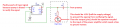
Hey guys I am a real noob at circuit designing. Here is an amplifier circuit I put together for a center channel subwoofer of a 2.1-channel USB-powered speaker system that I am planning to build. I basically made this circuit by binge-watching YouTube videos and following the IC's datasheet. Now I am in great confusion about the order of the sections labeled 1,2,3 in the image. Should the low pass go before the high pass or the preamp should go after the high and low pass, I don't know! Please help me out with it and please take a look at the circuit design for any flaws. I greatly appreciate any feedback you share.Schematic_TDA2822M Bridge Mode Circuit_2023-08-25.jpg
 

Papabravo

Joined Feb 24, 2006
21,345
The order is normally calculated from a set of requirements like the following:
  1. What is the maximum allowable attenuation in the passband? e.g. 0.5 dB in the passband.
  2. What is the minimum allowable attenuation in the stopband? e.g. -60 dB or better in the stopband.
  3. What is the width of the transition band? e.g. transition band of 3 KHz.
 

DickCappels

Joined Aug 21, 2008
10,247
Why do you think you need filters?

I would start by trying the circuit with your speakers and no filters. If it sounds like it needs some filtering, start with 1st order filters if it sounds like you need steeper response curves, increase the order of the filters.

It usually does not matter which filter goes first but it a good idea to put the preamp before the filters.
 

Audioguru again

Joined Oct 21, 2019
6,789
My speakers sound good that is why I have never used bass and treble filters.
Your filters can be used to cut lows and highs so the output sounds like a muffled old AM radio or old telephone.

The low output power TDA2822 is obsolete and is not made anymore. You might find a Chinese copy that might work poorly.
 

LowQCab

Joined Nov 6, 2012
4,356
With only a 5-Volt Power-Supply,
the Amp will probably be pushed pretty hard on a regular basis,
this is a situation where some Filtering can be of very noticeable benefit.

My suggestion would be to use a TDA7266, 497-3669-ND,
and then follow the Schematic in the Spec-Sheet exactly as shown.
.
.
.
 

Attachments

DickCappels

Joined Aug 21, 2008
10,247
My speakers sound good that is why I have never used bass and treble filters.
Your filters can be used to cut lows and highs so the output sounds like a muffled old AM radio or old telephone.

The low output power TDA2822 is obsolete and is not made anymore. You might find a Chinese copy that might work poorly.

TDA2822 is available from Electronic Source in Bangkok, they are about Us. $0.30 each and made by Unisonic Technolgies Co. LTD in Taiwan. I've been using Unisonic's components for more than 10 years and never had a complaint. Just because the chips are made by Chinese people does not tell you anything about the quality of the component. You have to look at the products themselves and the company.
 

Audioguru again

Joined Oct 21, 2019
6,789
Hi Dick. I forgot that Unisonic makes obsolete ICs designed by ST Micro. My datasheet of the TDA2822 is by ST Micro and is dated September 2003.
I have used and seen many National Semi and Texas Instruments audio amplifier ICs, but I have never seen a ST Micro or Unisonic one.
 

Audioguru again

Joined Oct 21, 2019
6,789
The bridged TDA2822 amplifier shown has a supply that is only 5V. Then the output power with 10% of clipping distortion (sounds awful) will be about 1W into an 8 ohms speaker, or 0.7W like a cheap clock radio with low distortion. It is not biased properly anyway so it is a rectifier.
EDIT: The LM358 is NEVER used for audio because it is noisy (hisss and rummble) and produces crossover distortion. It is not biased correctly then it rectifies the signal.
 
Last edited:

Thread Starter

ISHRAQ6251

Joined Aug 24, 2023
11
Don't see any need for a high pass stage. Are you expecting sub sonic signals on the input that you need to filter out?
I guess it's for DC noise cancelation. I don't know cause I just saw it somewhere on the internet and used it for good measure
 

Audioguru again

Joined Oct 21, 2019
6,789
Most opamps will oscillate when a 10uF capacitor is connected from its output to ground. That will happen because your P2 lowpass adjustment pot has a resistance much too low. Use a 10k pot in series with a 1k resistor and a 0.1uF capacitor to ground.

Here is the rectifying problem:
 

Attachments

Thread Starter

ISHRAQ6251

Joined Aug 24, 2023
11
The bridged TDA2822 amplifier shown has a supply that is only 5V. Then the output power with 10% of clipping distortion (sounds awful) will be about 1W into an 8 ohms speaker, or 0.7W like a cheap clock radio with low distortion. It is not biased properly anyway so it is a rectifier.
EDIT: The LM358 is NEVER used for audio because it is noisy (hisss and rummble) and produces crossover distortion. It is not biased correctly then it rectifies the signal.
What other options do I have other than LM358?
 
Top