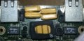
The devices pictured do look a lot like capacitors, but the markings do not look like any capacitor markings that I am familiar with. And what makes the picture more confusing is the "F22" and "F23" designations next to them. So it may be that they are not what they appear to be.
What would be quite useful is another picture giving a bit more background, and also a description of what sort of device is in the picture. And a picture of the underside of the board would help us understand a bit more about the connections, possibly helping to understand better.
Are you seeking replacements for these devices? If so, what appears to be the problem with them? If they are fuses, such as the PTC thermistor kind, they should show a fairly low resistance. And those devices do tend to look a lot like capacitors, but certainly they are totally different. The PTC devices are intended to serve a purpose similar to fuses, limiting fault currents by increasing their resistance a lot as they heat up when the current rises above some value. I don't recall the makers name, but it may be that is what the W/M logo will help with.
Now I see that others, also, are calling them PolySwitches. That indeed is the name.
I was running on the treadmill when I first replied. I revise my opinion and concur with @MaxHeadRoom and @dl324 that they are fuses. I wouldn't simply remove them, they are there to protect the ports from overcorrect for a reason.
Now I see that you intend to simply strip the boards for parts, so never mind.I was running on the treadmill when I first replied. I revise my opinion and concur with @MaxHeadRoom and @dl324 that they are fuses. I wouldn't simply remove them, they are there to protect the ports from overcorrect for a reason.