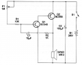
C2 100uF? Metronome circuit triggered when C1 charges to ~460mV. Vs can go down to 1.2V and up to limit of xstrs. C2 doesn't seem to have any function?
C2 100uF? Metronome circuit triggered when C1 charges to ~460mV. Vs can go down to 1.2V and up to limit of xstrs. C2 doesn't seem to have any function?
Put the scope on the Vs and it does not vary. Pulled C2 and no noticeable change in the output either on scope or audibly. Placing scope on the negative side of C1, I can see it rise in V until it reaches the trigger point ~460mV which does not change when C2 removed. Looking at it, I saw it as a Vs buffer but it doesn't seem to actually do anything. So I asked? When C1 triggers there is spiking and sagging of C1s input V as it triggers Q1 but it doesn't affect Vs even @ 1.2V. C2 looks like a good idea but doesn't seem to actually do anything so I asked.
C2 is power supply smoothing or reservoir capacitor.
When Q2 switches on, a large current flows to the speaker.
C2 supplies that current if the battery source resistance gets too high as it ages.
Years ago, I faced a problem of a pocket transistor radio squealing as the batteries got older. A check revealed that an electrolytic capacitor, positioned similar to C2, had dried out. Replacing it solved the problem.
I am sorry i though you were asking about C1 because the function of C2 is obvious.
So the question i have to ask now is the heck is this circuit used for?
It does not make any sense.
For one, who would want to bias a speaker with a DC current indefinitely. Even if it was for some sort of battery low detector it does not make sense to drain the battery that heavily just to detect a low battery condition.
So this leads me to ask:
Where did this circuit come from?
In the first post, first line, TS states that it is a circuit for a metronome.
This produces a "click" in the loudspeaker at frequencies selected in a range from 40 to 200 beats per minute.
In the first post, first line, TS states that it is a circuit for a metronome.
This produces a "click" in the loudspeaker at frequencies selected in a range from 40 to 200 beats per minute.
Oh ok then it does oscillate so C1 is for feedback and C2 makes the battery last longer due to the way the current drain vs the P factor for batteries works.
Careful that circuit is missing a base-current limit resistor, between Q1-C and Q2-B, like 1-10k.
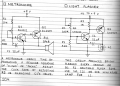
If you crank the pot low value, Q1 can stay on and roast. I first saw this kind of oscillator circuit in Forrest Mims collections as a blinky light circuit.
The book was published circa the 90s but the devices predate that by at least a couple of decades. I suspect he was not the original designer of these circuits and his word usage also suggests a much earlier period of time. I thought it may have been a reprint but doesn't appear to be so. Interesting book though with quite a few (~50) small projects. More developed circuits than the typical Mims et al.
I first built it around 1980, it goes back to the 1970's in Forrest Mim's books at Radio Shack which were great for learning.
Notice both circuits are missing the Q2 base resistor (I suggest 470R to 1k), the light blinky burns up the pot or kills the transistor, and both draw lots of current from the battery when the transistor is switching, much more than necessary. Too bad, it's a trap for newbies on a simple circuit.
I think this is why your circuit adds the 100uF cap across the battery, ripple there would be high with a small or weak battery.
A LOT of those old "Newbie" circuits were fraught with peril and not designed for actual usage. Which is not a good way to learn electronics... I do learn from my mistakes but being given a mistake as the "real thing" to learn from is pretty bad learning. And I am glad you pointed that out because I missed it. I did learn something from the C2 cap used with the battery. That was a new one on me.
No, C2 does not provide AC feedback. The purpose is just the opposite. C2 is intended to provide a constant low effective impedance so that the battery power supply voltage does not drop when the current pulse is delivered to the speaker. In simulations where power sources have zero source resistance it has no effect, but in the real world it is quite important.
No, C2 does not provide AC feedback. The purpose is just the opposite. C2 is intended to provide a constant low effective impedance so that the battery power supply voltage does not drop when the current pulse is delivered to the speaker. In simulations where power sources have zero source resistance it has no effect, but in the real world it is quite important.
Yeah but i already acknowledged that i thought he was asking about C1 because the reason for C2 is obvious a filter and makes the battery last longer. Read more posts.

 Facebook
 Google
 GitHub
 Linkedin