Facebook
 Google
 GitHub
 Linkedin

So if the sensor is outputting 96 mV, after the signal conditioning circuit, it should give 0 V . And that 0 V linearly increases to 1 V (being 3.7 V max. sensor output).
We learned about the Wheatstone bridge and Anderson loop, but I don’t know how to apply those with voltage (rather than an RTD like the book details). I would be happy to read any relevant online sources for ideas. I just keep running into potentiometer like circuits.
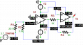
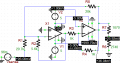
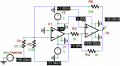
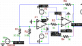
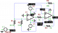
Could the Wheatstone or Anderson constant current loop work with a variable voltage like this? I did create an Anderson loop (previous project) with a RTD, but I don’t know what to change for a different configuration:

(That’s an instrumentation amplifier.) I realize this circuit has nothing to do with the problem posed.
I'm pretty lost.
What about a voltage divider to get rid of that 96mV, first?
0 = 0.096*R2/(R1+R2)…or no?
We learned about the Wheatstone bridge and Anderson loop, but I don’t know how to apply those with voltage (rather than an RTD like the book details). I would be happy to read any relevant online sources for ideas. I just keep running into potentiometer like circuits.
Could the Wheatstone or Anderson constant current loop work with a variable voltage like this? I did create an Anderson loop (previous project) with a RTD, but I don’t know what to change for a different configuration:
(That’s an instrumentation amplifier.) I realize this circuit has nothing to do with the problem posed.
I'm pretty lost.
What about a voltage divider to get rid of that 96mV, first?
0 = 0.096*R2/(R1+R2)…or no?
Last edited: