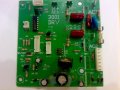
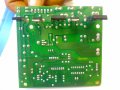
What does this circuit do?

Thread Starter

Engjay

Joined Mar 7, 2008
14
hi Guys
can anybody figure out what does this circuit do ?
i toke it from a tradmill near the dc motor
i want to know where the dc part is in this circuit
i need the schematic form for this circuit
i will attach the picture hope it can help
if u know any circuit that is similar to it
the names of the 6 chips
1-mospec u16c60c
2-kia 7805pi
3-cd 40106be h9605
4-ixys dsei 30-06A
5-st mrc tyn690
6-s21md3v sharp
thanks
 

Attachments

jpanhalt

Joined Jan 18, 2008
11,087
Given its location, I suspect it is a PWM controller for the DC drive onthe treadmill. If you look up each of the parts, you will probably get a better idea. Your #2 is a voltage reguator for the logic, the CD40106 is a hex Schmitt trigger from which the PWM signal is probably generated. John
 

Thread Starter

Engjay

Joined Mar 7, 2008
14
this circuit attached to a dc motor
our project is that we need to use battry without an ac input so we want to figure out how can we put the dc part so this circuit willl work
we want to remove the ac part
thats why we need the schematic for it
i dunno how to draw it
can you help me pleeez
 

jpanhalt

Joined Jan 18, 2008
11,087
Go here: http://www.alldatasheet.com/

Look up each of the components. I see at least 10 components, 5 on the back and 5 on the front. There is also a set of diodes on the board. One or more is probably a rectifier (maybe an SCR). Find that/those component(s) on the board and determine which lead is positive DC. There are tabs marked AC on the board. Are they at main's voltage (110 or 220V) or are they supplied from a transformer? I will assume they are main's voltage.

You say you want to use a battery. Some treadmills work at higher voltage than the usual 12V. Be sure to determine what voltage yours works at. The fact that there is no transformer on the board, and it is running a fairly powerful motor (As I recall, treadmill motors are around 1 HP) leads me to think the treadmill motor works on higher voltage DC.

The board also probably receives a DC logic-level supply through one of the plugs, as dropping from the rectified mains DC to logic with the 7805 is not going to work. You need to locate that other
circuit. Do you have a voltmeter? John
 

studiot

Joined Nov 9, 2007
4,998
i dunno how to draw it
can you help me pleeez
There is only one way.

Identify each component and its leads
Draw a block circuit diagram showing blocks for each component and connection stubs for the leads
Hold the board up to a strong light so you can see through it and
On your diagram draw the connections made by the tracks.

Redraw your diagram to bring out the circuit functions more clearly.

The board is one sided and there only seem to be macro sized components, so it should not be too difficult.

I would allocate 2/3 hours for the job.
 

Thread Starter

Engjay

Joined Mar 7, 2008
14
there is an external transformer from 220 to 110
we want to draw a circuit diagram for it
now i need to ask you
but if we neglect the AC part will it work perfectly
i mean does these stuff have some kind of a safety mechanism
we need your opinion we want this motor to work from a 12V battery
using a boost converter to 180V
or by inverting the 12V to AC around 220 and use it to power the whole system
which one is better
most of us are disagreeing on the 2nd idea so what do you think
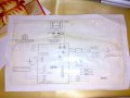
this is the diagram of how the system works and the info about the parts of the board
 

Attachments

Thread Starter

Engjay

Joined Mar 7, 2008
14
only if we configure that where is the ac part start and end and change to dc we can neglect it so we can make of use for this controller
thats why we need the schematic for it we tried to search but we have difficult to read the circuit
 

Attachments

jpanhalt

Joined Jan 18, 2008
11,087
we need your opinion we want this motor to work from a 12V battery
using a boost converter to 180V
or by inverting the 12V to AC around 220 and use it to power the whole system
which one is better
Any high-current boost converter from 12 VDC to 180 VDC will probably convert to AC, use a transformer, then convert back to DC. Since the last function is already built into the board you have, why do it twice? Convert the 12 VDC to 110 VAC and feed it to the board. John

Edit: Do you know the wattage of the motor you are trying to drive?
 

Thread Starter

Engjay

Joined Mar 7, 2008
14
is it better if we use a converter from dc to ac then using this circuit ?
so we are getting away from the ac part
but am scared that it will use more power
this project will be for our electric car
so we need this treadmill controller for controlling the speed for the car as it do when we using the treadmill we can increase it or we can decrease it
what do you think ???


we need it to attach the controller and dc motor for the electric car so we use battery
with 12 volt
 

Thread Starter

Engjay

Joined Mar 7, 2008
14
1.8 hp
dc motor
series 3000
with maximum volt in to 180 volt
so we can use a controller to 180 v for accelerating the motor
 
Top