What does this circuit do? Ac power line check?

Thread Starter

Steveisme

Joined Oct 2, 2024
15
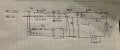
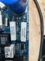
Hi, Im repurposing a treadmill motor and hoping to also use the motor control board as I know it is sized for the motor and has a lot of nice features. I’ve reverse engineered most of the board circuit and it’s all making sense, but there is one part that has me scratching my head (see attach pic of relevant circuit). It looks like circuitry to verify that there is AC power, which makes no sense because if there were no power then the microcontroller would not be running! So I’m guessing its purpose is to sense the quality of the AC source. It’s not a small amount of parts - it includes a couple large wire wound resistors and has a dedicated relay (K1) with driver logic (not shown), so they are pretty invested in this. Any insights? This came off a PaceMaster Platnum Pro treadmill. IMG_6921.jpeg
 

AlbertHall

Joined Jun 4, 2014
12,619
The 7W rating of those resistors makes no sense as the load includes a 100k series resistor.
Are you sure there is nothing else connected to the output of the rectifier?
 

Thread Starter

Steveisme

Joined Oct 2, 2024
15
Ooooh - good catch! There was one sneaky trace I missed connected between the rectifier and that 100k resistor. It connects into the main motor driver circuit to the BIG regulator and capacitor for the motor. I’ve added these to the schematic picture and also a picture of the board (if it helps). Im still not sure what the digital input to the microprocessor is sensing from this.
 

Attachments

Thread Starter

Steveisme

Joined Oct 2, 2024
15
The manual doesn’t really have any technical data and there is no schematic or detail I can find on line. This is why I am creating the schematic myself. I think my only hope is if there is someone on this forum that can interpret the schematic or has experience with this type of sensing.
 

MaxHeadRoom

Joined Jul 18, 2013
30,558
Does the motor itself have any kind of RPM detection etc?
I am assuming the nature of the motor is HV brushed DC? as is typical.
 

Thread Starter

Steveisme

Joined Oct 2, 2024
15
Yes, there is a tach unit on the motor that feeds into the microcontroller too. It is indeed a HV DC brushed motor.
 

michael8

Joined Jan 11, 2015
472
What's the AC line in voltage? The ratio of 100K & 2K divides the peak AC voltage in by about 50
so for 120 ac -> 160 peak -> about 3 V, or 240 ac -> 336 peak -> 6.7 V. It's some sort of
powerline sense. Clock function? Synch with zero crossing power function?
 

Thread Starter

Steveisme

Joined Oct 2, 2024
15
Yes, the input is 120VAC and I’m sure that the 100k and 2k resistors are all about dividing down the signal to provide a low level input to the microprocessor. It really seems to be some sort of sensor input to assess the quality of the AC input, but I’d really like to understand what it is sensing and how this particular circuit works to provide this input. I’ve not seen a regulator used this way before.

I’ll put a scope on it later to see if I can learn more about the input to the microprocessor. I’m also curious about when the processor enables the relay that enables this sensor.
 

Thread Starter

Steveisme

Joined Oct 2, 2024
15
Thanks! Always good to have safety reminders. Using an isolation transformer and best practices for sure!

So the plot thickens - K1 kicks on for only about a second each time the treadmill is commanded to start at the control panel. It then takes a couple more seconds before K2 kicks on to actually start the motor. During this time the DI goes from zero to 3.2v where it stays. It then slowly drops back to zero about 15-20 seconds after the motor is stopped (assume this is while the 2200uf discharges). I did notice that I can’t start again until the DI drops below about 1v - but this could just be a coincidence as the control panel may just not allow restart for a fixed amount of time. So it looks like the DI is doing some sort of check using the small regulator at startup and then doing a different check at the big regulator during run.

Have I stumped the band??
 

Thread Starter

Steveisme

Joined Oct 2, 2024
15
After a bit more reading about - I think what I have here is a soft start circuit. The small regulator with the big resistors are used to first charge the big cap and the sensing signal tells the processor when to switch off the soft start and switch over to the larger regulator for actual motor operation. Not sure if the sensor is ever used after start unless it’s to catch brownouts or to avoid quick restarts as mentioned in my last post (just a guess). I really wish I could get a look at the processor code!
 

MisterBill2

Joined Jan 23, 2018
27,164
The circuit could also be a mains voltage sense circuit. Think about the various supply types that accept both 120 VAC as well as 220 VAC, with no manual switching. So that could be possible. But "soft start" does make a lot of sense.
 

Thread Starter

Steveisme

Joined Oct 2, 2024
15
Hey, thought I’d provide an update in case someone is interested. I’ve taken quite a bit more measurements and have some additional data. Things are pretty complex because the ground for the two relays (tied together) is controlled by a signal from the control panel, and the +12v for the two relays is enabled by two different microprocessor DOs. Also, what I have been calling PIC DI is actually an analog input.

When the treadmill is started there is quite a dance of signals. The relay negative is disabled by the control panel and about 40ms later K1+ is enabled, but only for about 300ms and then it is dropped. I have no idea what this is all about - very interested if anyone has any ideas.

Then things start making sense. The relay negative is enabled about 150ms later. Then about 450ms later the K1+ is enabled. About a second later K1+ is dropped at which time the AI is about 2.9v. About 400ms later K2+ is enabled and then about 50ms later the PWM signal starts actually driving the motor. On stopping the treadmill the PWM % ramps down and after a few seconds K2+ is dropped. Not sure what triggers this delay - perhaps just time or could be motor speed from the tach input. The PWM signal continues about 5s and then stops at which time the AI is about 0.9v. I seem to be about to restart the treadmill at this time, but not before

Without looking at the code I really can’t tell if 1) the switchover to the big rectifier and 2) the stopping of the PWM signal are based just on time or based on the AI. But I’m guessing the AI is there for a reason and it seems likely it is used to determine when to switch over to the larger regulator at least.

I’m not really expecting any great insights here, but thought I’d share in the interest of thread closure.
 

Thread Starter

Steveisme

Joined Oct 2, 2024
15
One other oops - it’s actually the +12v signal of the two relays that are connected and controlled by the control board. The grounds are enabled by the microprocessor. So I should have used K1- and K2- rather than K1+ and K2+ above.
 

ajv

Joined Oct 15, 2024
5
I think that K1 will close first and the PLC will check the correct voltage before start. If you can connect and save the PLC software, inspect it and see what is doing with that input.
Big 82 ohm resistor are only to protect the circuit and limit the current, even if the rectifier will be shorted.
 

Thread Starter

Steveisme

Joined Oct 2, 2024
15
Thanks! I don’t have the tools to access the PLC software and it would be really tough to try and reverse engineer the raw assembly code. I’ve done that before for simpler systems, but this one has a ton of safety checks and interlocks and a pretty robust serial dialog with the control panel.

My whole goal in understanding the circuit is because I’d like to reuse the power board for a project and need to connect to an Arduino for control. I know a lot of people use these treadmill motors for shop projects by just hooking them to a PWM driver with a pot, but I need more control and I also wanted to take advantage of the many features on the board. So my options are 1) to reverse engineer the serial commands between this power board and the control panel, 2) to pull the PLC and build an Arduino “wart” that plugs in that I can program myself, or 3) modify the board to just use the power driver portion. I spent time looking at the serial lines and was able to reverse engineer most of it, but there is a ton of handshaking and checks that really would require seeing the processor software to be sure I understand and can operate safely. So, I’m going with option #2. I built the wart built using an RF Nano and I can run the motor with precision and communicate wirelessly to command its operation. The wart is really simple because the PLC and Arduino are both 5v devices, so all I had to do was connect the wires and add a couple filter caps just in case needed (but probably really don’t need since the wart is right on the motherboard that already has some near the PLC socket). I’m reading that power sense line to switch from the soft start circuit at the same voltage that was used by the PLC and all seems to be working great.

The only board mod I had to make (other than pulling out the PLC and inserting the wart) was to short two pins on one of the optical isolator outputs. As mentioned previously, the K1 and K2 relay coils get their ground enabled by the PLC but their +12v enable is from the control panel. I’m guessing this was another safety measure but pretty annoying! I could have enabled it by driving the control panel input, but that would have required also driving the power lines to the isolator and it was really easy just to short the isolator pins to ground the control signal - easy to undo if I ever decided to change course.

There are still a few things I don’t understand, like the odd motor start sequence that turns on each side of K1 independently before actually turning on both to enable. I also see that the analog voltage sense signal is also put back out to a quad op-amp based circuit that then feeds three other analog inputs to the PLC. Again, without the code I just have no idea what this circuit is doing. One of the quad op-amps is reading the elevation motor position pot, but the other three are doing some sort of additional processing on that voltage sense signal. I’m just using the signal direct and the timing all seems to match the original treadmill operation, but I would love to know what all that extra circuitry is for. This thread has not received a whole lot of attention, but if anyone thinks they might have an idea I can post the schematic for the op amp circuit. I’m just skeptical we can interpret what it is doing without the PLC code.
 

ajv

Joined Oct 15, 2024
5
A diagram will be welcomed.The motors on threadmilss are high voltage DC as I remeber,for finer speed control.So, you already know what the starting sequence is and can keep it as it is.
The PLC-HMI(panel) duo is classic, whatever functon are chosen from the panel,the PLC is giving the appropiate command to the motor.Supposed to have a torque control also, not only RPM control,acceleration limit and maybe inrush compensation.
The control mode is calculated for a motor with flywheel (most possible) or not.
Beside the motor's tacho there is an additional speed sensor?Because if yes, should taken in account.
And again the power "sense" circuit is only for starting, such circuits can be found, with different "look" in power supplies as a starting circuit.
K1 and K2 common pozitive are enabled when teh system is switched on, disabled during stand-by. Looks like the automotive electronics with relays activated to ground by ECM. And the pozitive also should be cut by the safety switch/key.
I think you have to check what signal (most probably analogue, unless the converter is digital) is PLC output to commands the motor converter.
And finally, there is not a real PLC, I think something like a PIC.If you can connect and read it, a ladder logic software will be usefull.
 
Top