I think they are differential digital inputs. One input sets the logic threshold (A2) and the other input is either HIGH or LOW with respect to that threshold.
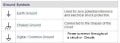
The power negative is generally used as the circuit common plane which is usually symbolized by the inverted triangle symbol, in some cases this can be connected to earth ground and the appropriate symbol is shown for this.
As per the PDF.
In N.A. the earth symbol is often misused as power common when it is actually not at earth ground. Also in N.A. ground is also used to indicate an earth conductor which further confuses the issue.
Max.
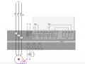
Actually taking another look it appears to be a PLC input module which is usually an opto input type, which would make the symbol in this case the two inputs of a Opto IC.
Max.
I assume by the IEC symbols you are not in N.A.?
If this is a PLC input, they just show the symbol as a representation of the input, you do not require to know the details.
Max.
If the OP confirms it is a PLC input then the opto representation makes perfect sense.
But the E-stop P.B. and output 04 N.C. contact actually confirms the power in.
If they were GND symbols the E-stop & 04 contact would short the power.
Input I.4 is a confirmation input.
Max.
A1 is the symbol for a fuse/breaker usually.
Found the manual for it and it is a TeSys LTM R unit which is a form of PLC if anyone cares to search.
A1 A2 are the power input, AC or DC.
The unit is a multi drop unit from a Modbus fed system, specifically for 3 phase motor monitoring.
Max.
The squiggle is not so common, but neither is that combination for a fuse. I assume that the squiggle meant an AC coil. With the START and STOP buttons, a relay makes sense. Can you show any examples of fuses that match that symbol?
Those are common IEC symbols, looking at the manual, it also appears to be used to indicate either AC or DC input, which the unit is according to the manual, in this case it seems a loose use of the symbol.
It is a amalgam of the symbols used on a AC/DC power source that can be either AC or DC.
The circuit is from the power through the output relay contact trough the E-stop P.B., both OR'd to an input, IOW an input monitoring the E-stop String, .
This apparently is not a common variable use PLC, but a Motor monitor specialized one.
The manual also states that the input block is just a symbolic representation of the inputs.
Max.
 Facebook
 Google
 GitHub
 Linkedin
 72.7 KB Views: 87