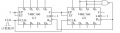
IC2 is going to produce a reset pulse via the Nand gate on a count of 6. If you want a 90 count, try connecting the Nand gate as an inverter directly to pin 15, the RCO pin. Tie both ENP pins permanently high.
It is SUPPOSED to reset both counters as soon as the right-hand counter's Q1 and Q2 outputs both go HI.
In practice, this is a very poor design and will be very susceptible to glitches.
The 74H160 is a synchronous counter, which means that all of the Q outputs change, nominally, at the same time. But in reality there will always be slight differences due to a host of factors. As a result, all possible transition paths need to be considered. For instance, when going from 3 to 4, the outputs are going from
Assuming equal probabilities for each path (which may or may not be a reasonable assumption), you can expect the NAND gate output to glitch LO about half the time.
The glitch only has to last long enough for the asynchronous reset to recognize and act on it, which might be only a few nanoseconds. This is much shorter than the maximum propagation delays from a clock input to a change in one of the Q outputs, which are in the dozens or even hundreds of nanoseconds. Thus, seeing differences in the propagation delays that are long enough for the reset to act is highly likely. It's also possible that width of the glitch pulse will be marginal and that only one or the other counter will act on it (and which one does is completely unpredictable).
More than likely, this is yet another example of a textbook circuit designed by someone that has never designed a circuit that had to work in the real world.
It is often helpful to provide a detailed question about the desired results of a circuit function, along with a description of what is happening instead. My ability to correctly guess what is wanted is quite limited.
It is SUPPOSED to reset both counters as soon as the right-hand counter's Q1 and Q2 outputs both go HI.
In practice, this is a very poor design and will be very susceptible to glitches.
The 74H160 is a synchronous counter, which means that all of the Q outputs change, nominally, at the same time. But in reality there will always be slight differences due to a host of factors. As a result, all possible transition paths need to be considered. For instance, when going from 3 to 4, the outputs are going from
Assuming equal probabilities for each path (which may or may not be a reasonable assumption), you can expect the NAND gate output to glitch LO about half the time.
The glitch only has to last long enough for the asynchronous reset to recognize and act on it, which might be only a few nanoseconds. This is much shorter than the maximum propagation delays from a clock input to a change in one of the Q outputs, which are in the dozens or even hundreds of nanoseconds. Thus, seeing differences in the propagation delays that are long enough for the reset to act is highly likely. It's also possible that width of the glitch pulse will be marginal and that only one or the other counter will act on it (and which one does is completely unpredictable).
More than likely, this is yet another example of a textbook circuit designed by someone that has never designed a circuit that had to work in the real world.
Depends on the device model more than the simulator (unless it's a pure-digital simulator, in which case the compatible models probably couldn't support the needed level of fidelity).
But it would be highly unlikely that anything other than a transistor-level subcircuit using a Monte Carlo simulation would produce them.
Another solution for an arbitrary count is to use the /load input as this is sync'd with the clock. So tying A-D to 0 and gating the <end_count> to pull /load low will load 0 on the next rising clock edge. This of course counts end_count + 1, so either gate for end_count-1, or simply set A1 = 1 and all other data inputs to 0.
 Facebook
 Google
 GitHub
 Linkedin
 \
\


 16.3 KB Views: 0


