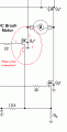
Weird N-Channel MOSFET symbol

Thread Starter

redbird_is

Joined Jan 13, 2008
11
I've come across a symbol that I don't recognize for an N-channel MOSFET.

As you can see in the picture, Q3 and Q4 use standard symbols, but Q2 has an extra wire (pin 4).

Is pin 4 just another source connection?


Thanks everyone
 

Attachments

mik3

Joined Feb 4, 2008
4,843
I've come across a symbol that I don't recognize for an N-channel MOSFET.

As you can see in the picture, Q3 and Q4 use standard symbols, but Q2 has an extra wire (pin 4).

Is pin 4 just another source connection?


Thanks everyone
I am not sure but i guess the connection with the arrow on it (opposite the gate) is a fourth pin connect to the substrate of the MOSFET, so you can control the substrate voltage. With the ordinary MOS the substrate is connected internally to the source.
 

Thread Starter

redbird_is

Joined Jan 13, 2008
11
I am not sure but i guess the connection with the arrow on it (opposite the gate) is a fourth pin connect to the substrate of the MOSFET, so you can control the substrate voltage. With the ordinary MOS the substrate is connected internally to the source.

Thanks for the reply. Yes, I agree that it must be some kind of substrate connection - perhaps it should be ignored when wiring (i.e. shouldn't actually wire the source to ground). Pin 4 may just be the one source connection.
 

John Luciani

Joined Apr 3, 2007
475
Those are sense-fets. That connection is used to sense the drain current.
A small portion of the die area is bonded to a separate pad. If the gate to source voltage
and gate to sense voltage match then the current out of the sense pin will be proportional
to the drain current. Using a sense FET lets you eliminate a current sensing resistor.

Search the IR and On-Semi websites for "sense fet" and you should be
able to find some application notes. If you can't find an app-note send me an email
and I will see if I have a local copy.

(* jcl *)
 

Thread Starter

redbird_is

Joined Jan 13, 2008
11
Those are sense-fets. That connection is used to sense the drain current.
A small portion of the die area is bonded to a separate pad. If the gate to source voltage
and gate to sense voltage match then the current out of the sense pin will be proportional
to the drain current. Using a sense FET lets you eliminate a current sensing resistor.

Search the IR and On-Semi websites for "sense fet" and you should be
able to find some application notes. If you can't find an app-note send me an email
and I will see if I have a local copy.

(* jcl *)

Thanks very much for the explanation, John. The circuit I'm building has a current sensing stage, so it makes sense that these sense FETs are used.
 

John Luciani

Joined Apr 3, 2007
475
is this type of FET used to clamp the current to a set point?
Since the sense current is proportional to the drain current you could create a circuit
that would reduce Vgs based on Isense.

The important thing is to keep the sense voltage the same as the source voltage
otherwise the Isense/Idrain ratio will change.

(* jcl *)
 
Top