Weird CAN bus waveform from STM32F4

Thread Starter

Damjan Dakic

Joined Sep 26, 2015
4
Hello,

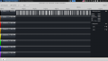
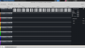
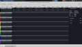
I am using two of STM32F415RG (more specifically http://www.mikroe.com/mini/stm32/). I made a CAN bus using MCP2551 as a transceiver and connected the two of them. They are successfully exchanging data. After that, I tried connecting a USB to CAN device so that my PC can also use the bus. The problem now is that the PC cannot exchange data with the microcontrollers. To try to debug everything I connected a Saleae logic analyzer and monitored the low line of the bus. Saleae Logic has a feature to decode CAN messages. It can successfully decode messages from PC but cannot decode messages from the microcontrollers. When I inspected the waveform the one generated by the microcontrollers looks very weird. I attached four screenshots, two are with the waveforms generated by a microcontroller and two are generated by the pc.

Here is my initialization code:
Code:
    g_canHandle.Instance = CANx;

    g_canHandle.pTxMsg = &g_txMessage;
    g_canHandle.pRxMsg = &g_rxMessage;

    g_canHandle.Init.TTCM = DISABLE;
    g_canHandle.Init.ABOM = DISABLE;
    g_canHandle.Init.AWUM = DISABLE;
    g_canHandle.Init.NART = DISABLE;
    g_canHandle.Init.RFLM = DISABLE;
    g_canHandle.Init.TXFP = DISABLE;
    g_canHandle.Init.Mode = CAN_MODE_NORMAL;
    g_canHandle.Init.SJW = CAN_SJW_1TQ;
    g_canHandle.Init.BS1 = CAN_BS1_14TQ;
    g_canHandle.Init.BS2 = CAN_BS2_6TQ;
    g_canHandle.Init.Prescaler = 16; //  125 kbps

    HAL_CAN_Init(&g_canHandle);
The pins are initialized correctly, as alternate function without pull. The bus is around 30cm long made from a twisted pair and terminated with 120Ohm resistor at each end. At the time of testing, only one MCU and UsbToCan were connected on the bus. Because they are waiting for ACK they are entering retransmission so that's the reason for so much data.

Thanks.
 

Attachments

Papabravo

Joined Feb 24, 2006
21,227
I believe that your problem is in the configuration of the bus timing parameters. The baudrates must be the SAME, and the sample point in the bit cell must be the same. One of the devices is throwing Error Active frames until it goes BusOff and the other device cannot finish the transmission, and receive the expected ACK, so it tranmits the frame forever. I'll bet large sums that the crystals used to derive the bit timing parameters in the USB to CAN device are different than the ones in the microcontrollers. This must be taken into account.
 

Thread Starter

Damjan Dakic

Joined Sep 26, 2015
4
Hi Papabravo, thanks for the reply.

I agree about the timings and everything else that you said, that makes sense. However, the timing on the MCU is most definitely correct. The main PLL is set so that the clock is 168MHz and this is correct because Uart for example is working properly when baudrate is set with this number in mind and delay function is also accurate. APB1 is set to divide by 4 which yields 42MHz going into the CAN module. According to the reference manual, fq/(BS1+BS2+1) is the frequency meaning 42MHz/21 = 2MHz. Prescaler is 16 which yields 125kbps as said. Saleae Logic analyzer cannot decode MCU data for which I am sure that the time is correct. Saleae however can decode data from UsbToCan. This is logical to me when I look at the waveform because the pulses generated by the MCU look unreasonably short (~70ns). Please take a look at the images I attached if you haven't already.

So to simplify the problem, let's say I'm not trying to get UsbToCan and MCU to communicate but I'm trying to get a correct waveform shape and get Saleae Logic analyzer to be able to decode the data.
 

Papabravo

Joined Feb 24, 2006
21,227
Baudrate is not the only thing to be concerned about. Where is the sample point located, and what is the allowed SJW (Synchronization Jump Width). These things must be identical on all nodes on a CAN Network, if you want the children to play nice on the network.

Also you should always look at both CAN Bus lines because it is the only way to tell if dominant is dominant and recessive is recessive.
 

Thread Starter

Damjan Dakic

Joined Sep 26, 2015
4
Papabravo, again, thanks for the reply. I am aware of the things you are saying but I think you still didn't look at the pictures I attached and are giving me generic CAN FAQ replies. I am looking at both can lines but CAN High is always on the same logical level.
 

Thread Starter

Damjan Dakic

Joined Sep 26, 2015
4
To be more precise, even if I change the baudrate and timing settings drastically, the pulse you can see on m2 never goes longer than 100ns.
 

Papabravo

Joined Feb 24, 2006
21,227
I don't know what, exactly, I'm looking at and I can't make any sense of it. I would need a schematic for the devices as well as other information difficult to provide in a forum post. What I do know is that CAN nodes, that vary the setup parameters, have little to no chance of working with each other. Both CAN lines must move for proper operation. In the beginning there was some talk of allowing one-wire CAN to work. The physical layer is quasi-differential with respect to a COMMON ground. There must be three wires between the nodes for things to work. The difference between CAN_H and CAN_L has to exceed some threshold in order for the node to see a dominant bit.

The original CAN nodes that my company made all had 16 MHz. oscillators. When we incorporated the 8051 into our product line we found that 18 MHz. was the oscillator of choice. We had to CAREFULLY reconstruct the CAN timing parameters to make the two nodes happy with each other. It can be done, but it requires some effort.
 
The timings are vital.
I also found that I couldn't get two slaves to work, I had to have master that took over control and send out a packet and received one.
Having two trying to send at the same time just resulted in the one with lowest address winning all the time.
 
Top