Wein bridge with varying frequency

Thread Starter

akis02

Joined Apr 30, 2011
57
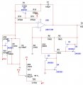
I have a wein bridge which works very well. I want to vary its frequency based on a square pulse every 1.5 seconds generated by an 555 (or perhaps an MCU).

The way to vary its frequency is to modify the "R" of the RC or the "C" of the RC.

But it has to be said, in order for it to oscillate at all, the two RCs must be almost perfect matches, even better than 1%. I actually pull components out of the draw and measure them and pair them, else it will not oscillate.

So we cannot willy-nilly mess with the Rs or the Cs and expect it to work.

To modify the "R" I thought of an LDR, actually two LDRs driven by the same LED. However LDRs have a varying resistance of many MOhm down to a few hundreds Ohms. I think it would be impossible to attempt to use two LDRs and expect them to either stay within a sensible range or to track each other to 1% or better. But I have a ton of LDRs so I may just try it.

Another idea was to mess with the Cs. For that the only thing I found was "varicaps" or "varactors". So I have bought a few to try out. Never used them before.

I am looking for ideas. Here is a schematic of the Wein bridge oscillator as it is and with the varactors in place which works on simulation. Simulation of course has perfect components so it does not prove anything.
 

Attachments

BobTPH

Joined Jun 5, 2013
8,804
How much does the frequency need to vary? A Wien bridge is not the best circuit for variable frequency. A phase shift oscillator would allow you to vary it by varying a single resistor, over a range of maybe 2 or 3 to 1.

Bob
 

Thread Starter

akis02

Joined Apr 30, 2011
57
+/- 10% that 's all.

A reason I use the Wein-bridge oscillator as in the schematic is its stability wtr temperature, the amplitude is really very stable.

I have never made a phase shift oscillator before, is that the one where you have 3 RCs in series something or other?
 

MikeML

Joined Oct 2, 2009
5,444
How much does the frequency need to vary? A Wien bridge is not the best circuit for variable frequency. A phase shift oscillator would allow you to vary it by varying a single resistor, over a range of maybe 2 or 3 to 1.

Bob
Hewlett and Packard had no trouble varying a Wein Bridge Oscillator (HP200A) over a 10:1 frequency range...

A Wein Bridge is a phase shift oscillator. It oscillates at the one frequency where the phase shift through the network is zero...
 

Thread Starter

akis02

Joined Apr 30, 2011
57
@AlphaDesign88
The wein bridge needs an amplification just over 3 to be able to oscillate, but as soon as it does it then hits the rails so you get a square wave rather than a sine. It also depends on the capabilities of the op-amp when it hits the rails how it will behave after.

But the idea is to limit it somehow so it does not hit the rails. The original design used a temperature positive coefficient resistor (aka light bulb) so that as the signal output increased so did the current in the bulb, the heat, the resistance increased and this applied the brakes and in the end it all equalised nicely without clipping.

In my design, it is not at all "all over the place", actually it is extremely sophisticated and as simple as possible. Not only I keep the wave form from clipping, but I also have tremendous temperature stability - my usual test is to blow a hair dryer on it until it reaches 80C and on the way there the waveform remains constant. I challenge anyone to produce such temperature stability from so few components.


@MikeML: yes but he used a dual gang, variable air capacitor. I want to use a voltage if possible.


Varactors arrived just now. I will try to test it on the breadboard somehow. I doubt it will work.
 

bertus

Joined Apr 5, 2008
22,270
Hello,

Perhaps a strange idea, but why not put a switched large capacitor parallel to the small one.
You could swtich it with a PWM signal using a bilateral switch like the 4066.
The PWM frequency should be 50 to 100 times higher as the highest wanted frequency.

Bertus
 
Last edited:

BobTPH

Joined Jun 5, 2013
8,804
Hello,

Perhaps a strange idea, but why not put a switched large capacitor parallel to the small one.
You could swtich it with a PWM signal using a bilateral switch like the 4066.
The PWM frequency should be 50 to 100 times higher as the highest wanted frequency.

Bertus
Or better yet, use DDS.

Bob
 

Thread Starter

akis02

Joined Apr 30, 2011
57
The varicaps have arrived but they are smaller than 0.5 mm in size, and I cannot use them. 40 new varicaps to a good home to whoever wants.

I am now experimenting with a jFET VCR in parallel with the Rs of the RC of the wein bridge. Works on simulation at least.
 

RichardO

Joined May 4, 2013
2,270
The varicaps have arrived but they are smaller than 0.5 mm in size, and I cannot use them. 40 new varicaps to a good home to whoever wants.

I am now experimenting with a jFET VCR in parallel with the Rs of the RC of the wein bridge. Works on simulation at least.
I would love to have the varicaps for an RF generator I am designing. Unfortunately, I am a wee bit more than a bicycle ride away. :D

About using J-FET's in the Wein bridge oscillator. How are you going to deal with the FET that uses the floating power supply?

If you still wanted to try to use those varicaps then you should reconsider the phase shift oscillator. The big advantage of the phase shift oscillator is that all of the all of the timing caps are connected to ground so it is easy to bias the varicaps.

Another possibility is to use an oscillator that uses integrators, such as a quadrature oscillator. The integrator resistor is referenced to ground -- actually virtual ground -- which makes driving the FET fairly easy.

Thinking of driving FET's reminded me of The National Semiconductor Linear Applications Handbook. It has a huge number of circuits, many of them using J-FET's. I would wager there is an example of just what you need.

I found a PDF of the 1994 edition on the Web. Be warned that it is 60 MB in size:
https://archive.org/details/NationalSemiconductorLinearApplicationsHandbook1994

I downloaded the PDF version but it is a scan so it can't be searched. Maybe one of the text versions would be searchable...
 

Thread Starter

akis02

Joined Apr 30, 2011
57
Cannot use the varicaps under any conditions since they are smaller than 0.5mm in size. I tried to solder lugs on one and it was impossible, the surface area is so small there is almost no mechanical strength on the solder joint and the lugs fall off.

I have implemented floating voltage by means of large gate resistors. Here is the schematic of the simulation, which works. But, yes let's not hold our breath for simulation, I need to breadboard it fist (soon).

The advantages of the Wein bridge which I have designed as in the first schematic are:
1) extremely steady amplitude wtr supply rails
2) extremely steady amplitude wrt temperature
3) very good frequency stability wrt rail supply and temperature
4) sine wave output

There is distortion whenever we use a jFET VCR unlike, say, using an LDR. I have a jFET matcher and hope to match the jFETs. Maybe I am dreaming. When I tried the LDRs they were non-linearly related, that means they had different curves of LED drive vs resistance. If I can match the LDRs they would be much preferable to jFETs due to 0% distortion added.
 

Attachments

RichardO

Joined May 4, 2013
2,270
There is distortion whenever we use a jFET VCR unlike, say, using an LDR. I have a jFET matcher and hope to match the jFETs. Maybe I am dreaming. When I tried the LDRs they were non-linearly related, that means they had different curves of LED drive vs resistance. If I can match the LDRs they would be much preferable to jFETs due to 0% distortion added.
Just a thought... Have you considered opto-couplers using FET's? Sorry, a part number does not come to mind.
 

Thread Starter

akis02

Joined Apr 30, 2011
57
The problem here is matching. A quick search on the net shows this is a 50 year old problem or older, seeking to make a VCR which is (a) linear (b) easy to match (c) floating (d) bi-directional ... and so on.

My best bet would be my own LED filed diagonally, glued on two LDRs which I have previously tried to match at 2-3 light points, hoping that glueing it on will result in same amount of light for both.
 
Top