Wave form lost when adding OP Amp

Thread Starter

captoro

Joined Jun 21, 2009
207
hello,

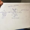
I have a circuit using an AD835, I am using it to do AM modulation the output is good. But I need to amplify that signal to 12v pk-pk. I added the LM7171 just as in this circuit: https://daumemo.com/final-pcb-for-the-diy-waveform-generator-part-10/
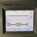
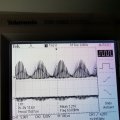
But when I hook up the output of my AD835 to the LM 7171, The signal from the source looses its negative part. and amplyfies only the positice, here is a picture before and after I hook up the LM7171.
Anyone has any ideas to resolve the issue and get full wave (-12 to +12) and no 0 to 12v ?

Ken
 

Attachments

MrChips

Joined Oct 2, 2009
30,701
You will have to show your circuit, not someone else's circuit off the internet.
Also a photograph showing your physical set up will also be useful for diagnosing your specific problem.
 

Thread Starter

captoro

Joined Jun 21, 2009
207
Hi.
My lm7171 is identical to the one on the link. My input is from an ad835 using 100ohm resistancevat it's output. Just as in the link . I could draw the circuit but it won't be different from what it's showing on the link. I don't get why the negative part of the wave from the source disappear!
 

MrChips

Joined Oct 2, 2009
30,701
How do we know that you have your circuit connected correctly? We are not there to see it.
We have not idea what you have in front of you.

Draw your circuit.
Show us a photo of your hardware.
 

KeithWalker

Joined Jul 10, 2017
3,063
The circuit diagram you posted is so small that I can barely read any of the labels.
What do you have connected to the "offset" input to the op-amp?
If you post a diagram of what you have built, that we can read, we may be able to help you.
Regards,
Keith
 

Thread Starter

captoro

Joined Jun 21, 2009
207
How do we know that you have your circuit connected correctly? We are not there to see it.
We have not idea what you have in front of you.

Draw your circuit.
Show us a photo of your hardware.
Here is the circuit I use. The negative and positive supply are from a dedicated power supply with transformer rectifier and bunch of lm780x and lm790x series. No switching supply. The purple wire is the input. Using 62khz carrier and 4khz modulator
 

Attachments

Thread Starter

captoro

Joined Jun 21, 2009
207
that the signal in pin.
I read 0.017 dc v with a multimeter.
If I read before the 100ohm resistor, at the output of the AD834 I have 0.04v. I am not sure how relevant that is considering its an average
 

MrChips

Joined Oct 2, 2009
30,701
Maybe the opamp is bad.
Since you are already using a breadboard why don't you try a different opamp (different part number) in an 8-pin DIP package?
This way we can clearly see how the pins are wired.
 

Ajith-N

Joined Sep 14, 2020
31
You shouldn't probe at the place you marked in your hand-drawn diagram, which is, the -ve input of the Opamp. The correct place to see the voltage output is the 'W' pin of the multiplier.

Clearly, your Opamp circuit isn't working. Disconnect the W and feed it (your Opamp Ckt!) with signal from a signal generator (with both +ve and -ve swings, make it similar to what you see at the W output, e.g. sinusoid with a similar frequency). Adjust the gain resistor as you need, make sure there is no output clipping etc. Then reconnect the W pin and check.

If your Opamp seems damaged, change it and repeat.

If nothing works, it could be the PCB and soldering. Clean out every bit of flux with IPA, scrub, brush, etc. In fact you should try cleaning your PCB first, as it seems hand soldered -- there is likely flux remnants floating around.

It could also be the breadboard effect. Your decoupling caps etc should be really close to the pins!
 

Thread Starter

captoro

Joined Jun 21, 2009
207
You shouldn't probe at the place you marked in your hand-drawn diagram, which is, the -ve input of the Opamp. The correct place to see the voltage output is the 'W' pin of the multiplier.

Clearly, your Opamp circuit isn't working. Disconnect the W and feed it (your Opamp Ckt!) with signal from a signal generator (with both +ve and -ve swings, make it similar to what you see at the W output, e.g. sinusoid with a similar frequency). Adjust the gain resistor as you need, make sure there is no output clipping etc. Then reconnect the W pin and check.

If your Opamp seems damaged, change it and repeat.

If nothing works, it could be the PCB and soldering. Clean out every bit of flux with IPA, scrub, brush, etc. In fact you should try cleaning your PCB first, as it seems hand soldered -- there is likely flux remnants floating around.

It could also be the breadboard effect. Your decoupling caps etc should be really close to the pins!
Hello.
I have change the chip for another lm7171.solders looks good. I have the same results.
 

Attachments

Top