 Facebook
 Google
 GitHub
 Linkedin
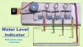
I tried today to build a simple water level indicator, but failed.I bought all these were from shop except charger.
BC 547 transistor
220 ohms resistor
5mm leds
9v charger but it is giving 12v might be this is a big problem for failing project.
I connected everything as in the image, but two leds were lighted themselves from starting and the other 2 were lighting when i touched the transistor center pin.
after sometime all the four leds are lighting by themselves. I think transistors are dead due to 12v, but let me know where the problem happened.
I am thinking the shop sold are poor quality components.
Attachments
-
 8.8 KB Views: 32


