Water Level Indicator with Microcontroller ..

Thread Starter

duck

Joined Sep 6, 2010
3
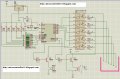
This is a circuit diagram I've taken from internet .. website <http://microcontroller51.blogspot.com/2010/03/microcontroller-at89c2051-8051-family.html>


Which Nand Gate Optocoupler can I use ?? Please Help ..
 

Attachments

KMoffett

Joined Dec 19, 2007
2,918
duck,

Not sure how you're planning on using the indicator, but the DC current through sense electrodes will cause them to corrode from electrolysis. This is not a problem in sensors that only rarely touch the water (like for sump pump controllers), but a problem for electrodes that are continuously submerged and conducting DC current. Better designs use AC to drive the electrodes.

Ken
 
Last edited:

SgtWookie

Joined Jul 17, 2007
22,230
Along the same train of thought as Ken's, you can avoid having the electrodes exposed at all. Air has a dielectric constant just slightly greater than 1 (very, very slightly greater), and water has a dielectric constant of roughly 78.

You could use a pair of single-sided copper-clad circuit boards that are conformal coated (think clear acrylic lacquer) that are held at a constant distance from each other using insulating spacers to create a home-made capacitor.

If there is just air between the plates, its' capacitance value will be small. As the water level increases, coming between more of the plates' area, the value of capacitance will increase considerably.

The capacitor could be used as the C part of an RC tank circuit, charged/discharged by one of the uC's I/O pins via a resistor.

Use a comparator input to trigger and capture the number of clock cycles elapsed when the cap is around 2/3 to 4/5 charged.

Since the plates are electrically insulated from the water in the tank, there is no need to use optoisolators, and only two I/O pins are needed for water level sensing.
 

KMoffett

Joined Dec 19, 2007
2,918
Have you tried to contact the blogger?

Looks like the NAND function is irrelevant, since the external inputs are fixed high. You just need an opto-coupler with an inverted logic output, or an open-collector output with a pull-up resistor. Even the inverted output isn't required since it's just a logic level call in a program. So almost any opto-coupler with a low I(f) for the LED might work.

Also, the conductivity of the water will be a big factor in whether it will work or not.

Ken
 
Top