 Facebook
 Google
 GitHub
 Linkedin
Hello everyone
I was hoping for some help if possible.
I have a clock from a late relative that was given to my uncle, it had corroded battery terminals so he cleaned them however snapped some wires in the process. He brought it to me to see if I could do anything.
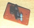
The clock has two wires for a trigger (I have probed these with a multimeter)
Two wires that go to a speaker.
Two wires from the battery.
Two wires from a switch (I assume this is to change the tone or silence it?)
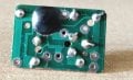
There is (I assume) a PIC under some epoxy.
A 4.7 uf Capacitor
A 5080 Transistor
A Resistor (not sure of the value)
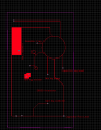
I have mapped the board out and also taken some pictures which are attached.
I was hoping someone with more knowledge than me would be able to help me map out which wires go where so I can restore the chime for my uncle.
From the research I have done I think that the cap and the transistor make an amplifier? to drive the speaker.
Thank you in advance
Grandmaster
I was hoping for some help if possible.
I have a clock from a late relative that was given to my uncle, it had corroded battery terminals so he cleaned them however snapped some wires in the process. He brought it to me to see if I could do anything.
The clock has two wires for a trigger (I have probed these with a multimeter)
Two wires that go to a speaker.
Two wires from the battery.
Two wires from a switch (I assume this is to change the tone or silence it?)
There is (I assume) a PIC under some epoxy.
A 4.7 uf Capacitor
A 5080 Transistor
A Resistor (not sure of the value)
I have mapped the board out and also taken some pictures which are attached.
I was hoping someone with more knowledge than me would be able to help me map out which wires go where so I can restore the chime for my uncle.
From the research I have done I think that the cap and the transistor make an amplifier? to drive the speaker.
Thank you in advance
Grandmaster
Attachments
-
 28.8 KB Views: 42
 -
 70.9 KB Views: 44
 -
 89.7 KB Views: 41
")


