Facebook
 Google
 GitHub
 Linkedin
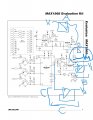
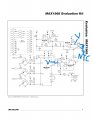
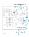
I have two sense two voltage which can vary from 0 - 1.5V maximum which i will send to microcontroller for display. One figure describe problem Second figure describe potential solutions in following figures :-
1) Voltage between 10Kohm and thermistor NTC . I think of only one option using the Voltage buffer than. Please tell if you have any other idea than voltage buffer to sense voltage. Which opam i should use for high accuracy. Also resistor should be use in feedback loop?
2) Set point voltage. I think of three options B,C,D. B, C option use voltage buffer while in option d we sense voltage directly. Please tell if you have any other idea than voltage buffer to sense voltage. Which opam i should use for high accuracy in B or C. Also resistor should be use in feedback loop?
Attachments
-
 222.1 KB Views: 20
 -
 257.4 KB Views: 21