Voltage Regulators - Problem 2

Thread Starter

PsySc0rpi0n

Joined Mar 4, 2014
1,755
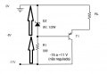
My next problem is attached...

Problem asks (a) for the voltage drop at R_Load and (b) if the hfe = 50, what is the max current that can be delivered to the Load!

V_in may vary from -15 V up to -11 V!

I was trying to write an equation to find the voltage at the node between the Zener and R1 but I'm making some confusion with the signs!

V_z + V_1 = V_in

Then:
V_z = 8 V
V_in = -11 V

V_1 = V_in - V_z
V_1 = -11 V - 8 V = -19 V, but this is not correct!

Where am I going wrong here?

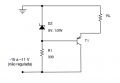
I know that by inspection, at R_1 must drop 3 V, because 8 V + 3 V of drop, matches the V_in supply voltage but I can't make the signs in the equation to match this value!
 

Attachments

hsazerty2

Joined Sep 25, 2015
32
V_z + V_1 = V_in
V_z is the voltage drop across the zener = 8v
V_in is overall voltage drop = 11v

-11v you used is the potential relative to the ground (0v) and not the voltage drop.

Remark:
If you replace the ground by +11v, and the -11v by 0v (you shift up all potentials by +11v), there will be absolutely no difference.
 

Attachments

Thread Starter

PsySc0rpi0n

Joined Mar 4, 2014
1,755
Ok, so if I want to evaluate I_R1, I should do:

I_R1 = (V_1 - V_in) / R1

I think V_1 = -V_z, right? Because if we think about the voltage drop direction, V_z is a voltage drop from the zener's cathode to the zener's anode, which is 8 V (positive because I'm saying that the voltage drop is in the same direction as the current direction I'm considering!). If I want to think about V_1, wrt GND, then I'll have -V_z = -8 V, no? Because in this case I'm considering the voltage drop at node 1 (same node as the zener's anode) to the node labelled as GND and this direction is the opposite of the zener's current direction!

So, if that is correct:

I_R1 = (V_1 - V_in) / R1
I_R1 = (-8 V - (-11 V)) / 330 = 9.09 mA

But looks like this is not correct!
 
Last edited:

grahamed

Joined Jul 23, 2012
100
Conventional current goes from positive to negative (outside the cell if we are being pedantic), including that which flows through a zener.

In a more usual circuit it would flow from a positive rail to a (less positive) 0V (downwards) and would have a positive value.

In this circuit the current flows from 0V to a more negative rail; the current through Z and R1 will be downhill and still positive value.

For any component with either positive or negative rails or both, and provided the circuit is drawn going positive to negative top to bottom -

take the voltage at the more positive end (top), subtract the voltage at the less positive (bottom) (taking notice of signs of course), divide by the resistor

I_R1 = (Vz - Vin) / R1
= (-8 - (-11) ) /R1
= 3/R1 A

all this stuff about voltage drops and thinking about wrt to zero confuses me......all voltages are wrt to zero except voltage drops (drop => downhill) which are wrt to the less positive voltage, but still positive. zeners and resistors don't do negative voltage drops.

In the olden days when transistors were Germanium you would sometimes find a circuit drawn with negative at the top - this was mind-blowingly confusing.
 

grahamed

Joined Jul 23, 2012
100
and current goes in the direction of the arrow in any forward biassed junction therefore down hill and so the arrow points downhill. zeners are of course reverse biassed.
 

Thread Starter

PsySc0rpi0n

Joined Mar 4, 2014
1,755
But the current value of 9.09 mA for R1 is not matching LTSpice which is saying that this current is 7.98 mA.

Ok, the zener I chose has a Vz = 8.2 V.

So, redoing the calcs:

V_R1 = V_in - V_z
V_R1 = -11 V - (-8.2 V)
V_R1 = -2.8 V (2.64 V in LTSpice)

I_R1 = V_R1 / R1 = -2.8 V / 330 Ω = -8.48 mA (7.98 mA)
 

grahamed

Joined Jul 23, 2012
100
But the current value of 9.09 mA for R1 is not matching LTSpice which is saying that this current is 7.98 mA.

Ok, the zener I chose has a Vz = 8.2 V.

So, redoing the calcs:

V_R1 = V_in - V_z
V_R1 = -11 V - (-8.2 V)
V_R1 = -2.8 V (2.64 V in LTSpice)

I_R1 = V_R1 / R1 = -2.8 V / 330 Ω = -8.48 mA (7.98 mA)
 

hsazerty2

Joined Sep 25, 2015
32
@Jony130
When i say there is no difference, i mean all the voltage drops across all the components will be the same, the circuit will not notice anything;
but of course all potentials will be shifted up by 11v; The base voltage was -8v (relative to old ground), after shifting, the new value relative to the new ground will be 3v.

@PsySc0rpi0n
Well, you get the idea, but when you say voltage drop, it's always between two points (nodes), or across a component; you say voltage drop between node A and B, across a resistor, a zener, a capacitor,....etc.

you can't say voltage drop at node 1, you say the potential (or just voltage) of node 1 (relative to a reference ground).
Here the voltage drop across the 330 resistor is :
BaseVoltage - CollectorVoltage = -8v-(-11v) = 3v
 

Thread Starter

PsySc0rpi0n

Joined Mar 4, 2014
1,755
Any small difference in currents is due to LTSpice modelling the zener.

Does LTspice say -7.98mA or 7.98mA?
Well, it depends on how I place the resistor. If I place it just like I pick it up from the list, it will have one direction, though, current will be either positive or negative. But If I rotate the resistor by 180º, the current will have the opposite sign/direction! So, it's kinda hard to answer that. Also, sometimes, not sure why, maybe by convenience, LTSpice plots negative values without me asking for!

But without rotating the resistor, the current is 7.98 mA (positive), from node 1 to Vin!

@PsySc0rpi0n
Well, you get the idea, but when you say voltage drop, it's always between two points (nodes), or across a component; you say voltage drop between node A and B, across a resistor, a zener, a capacitor,....etc.

you can't say voltage drop at node 1, you say the potential (or just voltage) of node 1 (relative to a reference ground).
Here the voltage drop across the 330 resistor is :
BaseVoltage - CollectorVoltage = -8v-(-11v) = 3v
Ok, so, I'll assume that my value of I_R1 = -8.48 mA is correct. Nevermind if it's positive or negative. The problem is if I, at the middle of the problem/calcs, miss consistency in analyzing the circuit. I'll end up with wrong calcs!
 

grahamed

Joined Jul 23, 2012
100
Yeah, I already spotted that one.

If I'm saying that Vin = -11 V, which is wrt GND, then V_z = -8V, also with respect to GND!
Yes, all absolute voltages are wrt 0V, which is to say if we don't specify a reference it is zero. This is true for the real world also. If I say I am 1850mm tall (positive) then I hope you would assume I meant from the ground upwards, and if I said the sewer was 3m down (negative).....
 

Thread Starter

PsySc0rpi0n

Joined Mar 4, 2014
1,755
@PsySc0rpi0n
HOW YOU PUT THE RESISTOR DOES NOT CHANGE ANYTHING.
Whether you get a positive or negative value only depends on how you insert your probe.
You don't need capitals. I can see clearly the small letters!

If you probe one resistor in one way, and then flip the resistor by 180º and probe it again in the very same way, you'll get a shift in the sign!
 

grahamed

Joined Jul 23, 2012
100
You don't need capitals. I can see clearly the small letters!

If you probe one resistor in one way, and then flip the resistor by 180º and probe it again in the very same way, you'll get a shift in the sign!
Yes, If the probes are attached to the same ends of the resistor, but you have now connected your meter backwards so whilst it might read minus something it is telling you positive something - in the old days it would also be telling you that your meter is now dead.
 
Top