Facebook
 Google
 GitHub
 Linkedin

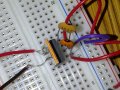
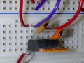
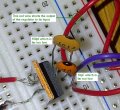
You have everything connected WRONG:
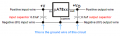
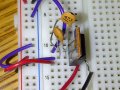
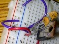
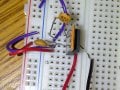
1) The negative black wire from a battery or power supply connects to the purple wire that wrongly connects to the OUTPUT pin of the regulator. But it is supposed to connect to the ground wire of the circuit.
2) The capacitor marked "102" is only 0.001uF(1000pF or 1nF) which is also much too small. It has both of its wires wrongly shorted together at the input pin of the regulator. One of its wires is supposed to connect to the ground wire of the circuit.
3) The ground pin of the regulator and one wire of the output capacitor is the ground wire of the circuit but they wrongly do not connect to anything. They are supposed to connect to the negative black wire from the input power supply and to the ground wire of the output load.
What is the other red wire and the black wire for? The red wire connects to the input pin of the regulator and the black wire connects to the output pin of the regulator so they connect to the input power supply.
1) The negative black wire from a battery or power supply connects to the purple wire that wrongly connects to the OUTPUT pin of the regulator. But it is supposed to connect to the ground wire of the circuit.
2) The capacitor marked "102" is only 0.001uF(1000pF or 1nF) which is also much too small. It has both of its wires wrongly shorted together at the input pin of the regulator. One of its wires is supposed to connect to the ground wire of the circuit.
3) The ground pin of the regulator and one wire of the output capacitor is the ground wire of the circuit but they wrongly do not connect to anything. They are supposed to connect to the negative black wire from the input power supply and to the ground wire of the output load.
What is the other red wire and the black wire for? The red wire connects to the input pin of the regulator and the black wire connects to the output pin of the regulator so they connect to the input power supply.
Last edited: