I want to design a circuit that required total 8A, 5V DC, powered by a car battery 12V, any suggestion of power regulator or circuitry?
can I parallel a few zener diodes to obtain the required current and maintain the voltage?
I want to design a circuit that required total 8A, 5V DC, powered by a car battery 12V, any suggestion of power regulator or circuitry?
can I parallel a few zener diodes to obtain the required current and maintain the voltage?
I want to design a circuit that required total 8A, 5V DC, powered by a car battery 12V, any suggestion of power regulator or circuitry?
can I parallel a few zener diodes to obtain the required current and maintain the voltage?
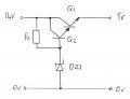
Below is a linear circuit that will supply 5Vdc at 8A from a 14Vdc supply, but it will dissipate 72W of lost power – which is why a buck circuit is preferable.
Transistor Q1 is a 2N3055 (TIP3055) type – its gain can be as low as 5, therefore transistor Q2 should have a collector current rating of at least 1.6A. Although transistor Q1 will dissipate the lion’s share of the 72W (and will need heatsinking), transistor Q2 could dissipate up to 14W and may also need a heatsink.
R1 is a 100 ohm 1W resistor, DZ1 is a 0.5W 6.2V zener diode.
Circuit values are based on 14Vdc (rather than 12Vdc) which is representative of the vehicle voltage with the engine running – and should operate OK down to 10Vdc or less.
If you want the circuit to operate at a lower input voltage – use a 1.3W rated zener diode and a resistor R1 of 39 ohm 2W.
You could add a capacitor in parallel with the zener diode to reduce any electrical noise on the 5V supply.
Although not shown, some form of fusing/over current protection should be included to protect the circuit in the event of an overload/short circuit.
A lot of dissipation at 8A, a series pass will dump the full 12V into the load if it fails - this is also true of the buck type switcher, but more reliable cool operation is much easier.
Below is a linear circuit that will supply 5Vdc at 8A from a 14Vdc supply, but it will dissipate 72W of lost power – which is why a buck circuit is preferable.
Transistor Q1 is a 2N3055 (TIP3055) type – its gain can be as low as 5, therefore transistor Q2 should have a collector current rating of at least 1.6A. Although transistor Q1 will dissipate the lion’s share of the 72W (and will need heatsinking), transistor Q2 could dissipate up to 14W and may also need a heatsink.
R1 is a 100 ohm 1W resistor, DZ1 is a 0.5W 6.2V zener diode.
Circuit values are based on 14Vdc (rather than 12Vdc) which is representative of the vehicle voltage with the engine running – and should operate OK down to 10Vdc or less.
If you want the circuit to operate at a lower input voltage – use a 1.3W rated zener diode and a resistor R1 of 39 ohm 2W.
You could add a capacitor in parallel with the zener diode to reduce any electrical noise on the 5V supply.
Although not shown, some form of fusing/over current protection should be included to protect the circuit in the event of an overload/short circuit.
The cascading may be good but generate a substantial heat don’t they; the output of a buck circuit will have some ripple, if I were to improve the output wave, would it better to shunt a cap prior to the main circuit?
The cascading may be good but generate a substantial heat don’t they; the output of a buck circuit will have some ripple, if I were to improve the output wave, would it better to shunt a cap prior to the main circuit?
I wouldn't even call that circuit a voltage regulator. The voltage will vary too much with changing load. A linear regulator, like 7805, with an external pass transistor will give much better regulation.
Ripple from switching regulators is straightforward to filter. If you're worried about a few tens of millivolts of ripple, several tenths of a volt should really concern you.
It can with the external pass transistor I mentioned.
Using this circuit from a National Semiconductor Voltage Regulator Handbook, you can set the current division between the regulator and pass transistor:
 Facebook
 Google
 GitHub
 Linkedin
")