 Facebook
 Google
 GitHub
 Linkedin
Hey guys, we were shown a circuit in class recently for ac rectification using an opamp.
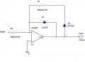
Looking this circuit up on the net found this:

WHich makes perfect sence to me.
The problem I am having is the variant we got in class. The problem circuit can be seen as an attachment to this post.
The problem I am having is the opamp tries to make the voltages at both inputs the same. So the inverting input should nearly become zero volts. For As it will still be fractionally positive (once in balance) the output of the opamp, in my mind will be -0.7 volts, otherwise the diode would not conduct. In my notes when the input is positive the output is 0. I can see how this occurrs in the above schematic but not in my attachment.
Thanks!
Looking this circuit up on the net found this:
WHich makes perfect sence to me.
The problem I am having is the variant we got in class. The problem circuit can be seen as an attachment to this post.
The problem I am having is the opamp tries to make the voltages at both inputs the same. So the inverting input should nearly become zero volts. For As it will still be fractionally positive (once in balance) the output of the opamp, in my mind will be -0.7 volts, otherwise the diode would not conduct. In my notes when the input is positive the output is 0. I can see how this occurrs in the above schematic but not in my attachment.
Thanks!
Attachments
-
 10.2 KB Views: 23
Last edited:
") ! Usually I hear more "categorical" opinions...
! Usually I hear more "categorical" opinions...


