Voltage drop on circuit of capacitors

Thread Starter

Capponero

Joined Nov 6, 2017
6
Hi guys,

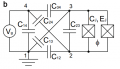
can you recommend the software, which would give me the ratio of the voltage drop on Cj to input voltage according to attached scheme? I tried to use Simetrix for it, but it had some problems with floating node or a loop of voltage sources.

Cheers,
Cappo
 

Attachments

WBahn

Joined Mar 31, 2012
32,998
You will probably have floating node problems in LTspice, too.

There's no DC path to ground for Nodes 2 and 3.

You can resolve this either by putting appropriate initial conditions on those nodes, or putting something like a resistor to those nodes that is sized so that it has negligible impact on the behavior. Something like 1 GΩ resistors usually work well.
 

ErnieM

Joined Apr 24, 2011
8,415
LT spice can handle differential voltage measurements.

If your package does not, just put the ground symbol where it is more useful for your needs.

And while you're at it, untwist the unnecessary twist in that schematic.
 

MrAl

Joined Jun 17, 2014
13,730
Hi guys,

can you recommend the software, which would give me the ratio of the voltage drop on Cj to input voltage according to attached scheme? I tried to use Simetrix for it, but it had some problems with floating node or a loop of voltage sources.

Cheers,
Cappo
Hi,

Is Vg a true voltage source? If so cap C14 is eliminated.
 

WBahn

Joined Mar 31, 2012
32,998
I don§t understand. Why it would be eliminated?
It's eliminated in the sense that it has no influence on the behavior of the rest of the circuit. The voltage source forces the voltage across that capacitor to be whatever the source voltage is.
 

MrAl

Joined Jun 17, 2014
13,730
I don§t understand. Why it would be eliminated?
Hi,

Well i assume that you are looking for a voltage response somewhere in the circuit not a current response because that is what your question sounds like.

As WBahn said, an ideal voltage source forces the cap to have the same voltage as the voltage source, so if you remove the cap you still get the same voltage across that cap position (the two nodes). This means any other voltage in the circuit like the one you are looking for will not change when you remove the cap.

If you are looking for the current response for the source though then you have to keep the cap in there because it does draw current from the source as long as the source is changing. That does not seem to be what you are looking for however so the cap can be removed to simplify the circuit just a little bit.
 

Thread Starter

Capponero

Joined Nov 6, 2017
6
Thanks a lot guys. It helped a lot. One more question: do any of you have an idea how to calculate the voltage ratio analytically? I mean, according to Thevenin's theorem the scheme can be replaced by analogical scheme with just two capacitors - one in series and one to ground, but I kind of stuck with the capacitance of those capacitors calculation.

Thanks
 

MrAl

Joined Jun 17, 2014
13,730
Thanks a lot guys. It helped a lot. One more question: do any of you have an idea how to calculate the voltage ratio analytically? I mean, according to Thevenin's theorem the scheme can be replaced by analogical scheme with just two capacitors - one in series and one to ground, but I kind of stuck with the capacitance of those capacitors calculation.

Thanks
Hi,

Some circuits are harder to do that way than others. When the components can be combined easily that way works pretty well, but when they cant be combined it turns into a full circuit analysis problem unless maybe you want to look into other ways of combining like delta to wye or vice versa.

For one example, if you use Nodal analysis you can calculate the complex current into the top left node from the voltage source, then calculate the input impedance (which turns out to be capacitive of course) by using:
Zin=Ein/Iin

and you get an expression like this:
Zin=A/(B*s)

and since the impedance of a cap is:
zC=1/(s*C)

that means the capacitance of the circuit must be:
Cin=C=B/A=1/(s*Zin)

So the steps would be:
1. Use Nodal or some other analysis to solve the circuit.
2. Calculate input current Iin.
3. Form the division Zin=Ein/Iin and equate Zin=A/(B*s).
4. Calculate Cin=B/A.

This is for the input capacitance only. It wont come out that clean if there is also resistance and/or inductance in the circuit too.

For a numerical example, i get something very close to 3.14 Farads as the input capacitance if each capacitor value is made equal to it's numerical part number divided by 10. For example:
C12=1.2 Farads
C13=1.3 Farads
C14=1.4 Farads
C23=2.3 Farads

etc.

Note the symbolic input capacitance formula has all the capacitors in it because each and every one plays a part in the total input capacitance and so it is a big expression. It only simplifies if some of the caps are the same value, and if all are the same value then it will simplify a lot. In fact, if they are all the same value the input capacitance comes out to:
Cin=2*C

if i remember right, or something simple like that, but they must ALL be the same value C to get that simple result.
 
Last edited:

Thread Starter

Capponero

Joined Nov 6, 2017
6
Hi,

Some circuits are harder to do that way than others. When the components can be combined easily that way works pretty well, but when they cant be combined it turns into a full circuit analysis problem unless maybe you want to look into other ways of combining like delta to wye or vice versa.

For one example, if you use Nodal analysis you can calculate the complex current into the top left node from the voltage source, then calculate the input impedance (which turns out to be capacitive of course) by using:
Zin=Ein/Iin

and you get an expression like this:
Zin=A/(B*s)

and since the impedance of a cap is:
zC=1/(s*C)

that means the capacitance of the circuit must be:
Cin=C=B/A=1/(s*Zin)

So the steps would be:
1. Use Nodal or some other analysis to solve the circuit.
2. Calculate input current Iin.
3. Form the division Zin=Ein/Iin and equate Zin=A/(B*s).
4. Calculate Cin=B/A.

This is for the input capacitance only. It wont come out that clean if there is also resistance and/or inductance in the circuit too.

For a numerical example, i get something very close to 3.14 Farads as the input capacitance if each capacitor value is made equal to it's numerical part number divided by 10. For example:
C12=1.2 Farads
C13=1.3 Farads
C14=1.4 Farads
C23=2.3 Farads

etc.

Note the symbolic input capacitance formula has all the capacitors in it because each and every one plays a part in the total input capacitance and so it is a big expression. It only simplifies if some of the caps are the same value, and if all are the same value then it will simplify a lot. In fact, if they are all the same value the input capacitance comes out to:
Cin=2*C

if i remember right, or something simple like that, but they must ALL be the same value C to get that simple result.
Hi, thanks for long reply. So you are saying that final formula will be complicated. However, from that you have said I got that it should be set of few equations with the same number of variables. Am I correct? If yes, do you also have some advice how to write those equations?

Thanks in advance
 

MrAl

Joined Jun 17, 2014
13,730
Hi,

Well you could write nodal equations to start with.

First, convert all capacitors to impedances by replacing C14 with 1(s*C14) for example. C24 would go to 1/(s*C24). The only difference here is now the 'C' is in the denominator and it is also multiplied by the variable 's'. So we now have impedances:
zC14, zC24

or if you like to call them:
z14, z24

that's fine too. We just proceed as nodal now.

The current through any cap is now the difference in node voltages divided by the impedance. So the current through C14 is:
Vg/z14

or in terms of the node numbers you have there we would have:
(v4-v1)/z14

and since v1=0 we end up with:
v4/z14

and since v4=Vg we get:
i14=Vg/z14.

The current through C24 is:
(v4-v2)/z24

and since v4=Vg we have:
i24=(Vg-v2)/z24

The current through C34 is:
(v4-v3)/z34

and again v4=Vg so we get:
i34=(Vg-v3)/z34

The input current is then:
Iin=i14+i24+i34

We also have to compute the current for the nodes 3 and 2, and solve for the voltages there. That allows us to calculate the actual input current as above. We then divde:
Zin=Vg/Iin

and then go from there. We then get this into the form:
Zin=A/(s*B)

and so the input impedance is capacitive and is:
Cin=B/A

We can probably do this or we could do a simpler example first? That would be faster.
In fact, if we do a single cap that may illustrate.

The single cap impedance is:
zC=1/(s*C)

The input current is:
Iinn=Vg/zC

so:
Iin=Vg/(1/(s*C))=Vg*s*C

and the input impedance calculated is:
Vg/Iin=Vg/(Vg*s*C)=1/(s*C)

and in the form A/(s*B) we have:
A=1
B=C

so the cap value is B/A:
Cin=B/A=C/1=C

and this makes sense because it is just one capacitor.

If you dont now how to do Nodal though you'll have to look into that or we could do an example here. If you know how to do it with resistors then you know how to do it with capacitors.

Notice if C14 was a resistor R14 the current through it would be Vg/R14 amps.

If we replaced all the caps in the original circuit with resistors could you solve it then for the total input resistance? If not, we should do that first then, then you could jump right to the caps after that.
 

Thread Starter

Capponero

Joined Nov 6, 2017
6
Hi,

Well you could write nodal equations to start with.

First, convert all capacitors to impedances by replacing C14 with 1(s*C14) for example. C24 would go to 1/(s*C24). The only difference here is now the 'C' is in the denominator and it is also multiplied by the variable 's'. So we now have impedances:
zC14, zC24

or if you like to call them:
z14, z24

that's fine too. We just proceed as nodal now.

The current through any cap is now the difference in node voltages divided by the impedance. So the current through C14 is:
Vg/z14

or in terms of the node numbers you have there we would have:
(v4-v1)/z14

and since v1=0 we end up with:
v4/z14

and since v4=Vg we get:
i14=Vg/z14.

The current through C24 is:
(v4-v2)/z24

and since v4=Vg we have:
i24=(Vg-v2)/z24

The current through C34 is:
(v4-v3)/z34

and again v4=Vg so we get:
i34=(Vg-v3)/z34

The input current is then:
Iin=i14+i24+i34

We also have to compute the current for the nodes 3 and 2, and solve for the voltages there. That allows us to calculate the actual input current as above. We then divde:
Zin=Vg/Iin

and then go from there. We then get this into the form:
Zin=A/(s*B)

and so the input impedance is capacitive and is:
Cin=B/A

We can probably do this or we could do a simpler example first? That would be faster.
In fact, if we do a single cap that may illustrate.

The single cap impedance is:
zC=1/(s*C)

The input current is:
Iinn=Vg/zC

so:
Iin=Vg/(1/(s*C))=Vg*s*C

and the input impedance calculated is:
Vg/Iin=Vg/(Vg*s*C)=1/(s*C)

and in the form A/(s*B) we have:
A=1
B=C

so the cap value is B/A:
Cin=B/A=C/1=C

and this makes sense because it is just one capacitor.

If you dont now how to do Nodal though you'll have to look into that or we could do an example here. If you know how to do it with resistors then you know how to do it with capacitors.

Notice if C14 was a resistor R14 the current through it would be Vg/R14 amps.

If we replaced all the caps in the original circuit with resistors could you solve it then for the total input resistance? If not, we should do that first then, then you could jump right to the caps after that.
I am going to try it, but I am really confused about what guys above said, that if it is true voltage source, we can ignore capacitor C14. But ignoring resistor R14 in alternative scheme doesn't seem well. What I am doing wrong?
 

WBahn

Joined Mar 31, 2012
32,998
Thanks a lot guys. It helped a lot. One more question: do any of you have an idea how to calculate the voltage ratio analytically? I mean, according to Thevenin's theorem the scheme can be replaced by analogical scheme with just two capacitors - one in series and one to ground, but I kind of stuck with the capacitance of those capacitors calculation.

Thanks
The answer should be yes, but first we need to know just what Ej and Φ are in your original schematic?
 

WBahn

Joined Mar 31, 2012
32,998
I am going to try it, but I am really confused about what guys above said, that if it is true voltage source, we can ignore capacitor C14. But ignoring resistor R14 in alternative scheme doesn't seem well. What I am doing wrong?
If C14 were R14, the same thing would apply. The resistor has no impact on the rest of the circuit. The only thing it impacts is the current in Vg.
 
Top