Voltage Dividers. Parameters for Median Point

Thread Starter

way5

Joined Apr 29, 2019
3
Greetings everyone!
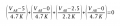
I have two voltage dividers that formed by resistors as shown on the attached photo. Could anyone help me to find out the formula that describes correct parameters for median point that marked as "?".
Wire resistances neglected.

Thanks~

2021-09-23 16.43.34.jpeg

PS: Didn't know where to publish my noobish question hopefully the topic is not mistaken for this thread.:)
 

Papabravo

Joined Feb 24, 2006
21,225
The lower resistors are in parallel, but the upper resistors are connected to different potentials. Compute the parallel combination of the lower resistors and then use superposition to compute the currents in the upper resistors.
 

RBR1317

Joined Nov 13, 2010
714
Whenever you don't know what tricks or transformations to use, there is always nodal analysis, which is based on the simple proposition that the sum of currents flowing at a node must equal zero. This problem has a single node with an unknown voltage, but multiple names (A & B), and four resistors connected to the node - therefore 4 currents are flowing at the node.

The general form for each current flowing at the node is:

(Voltage at node) -(Voltage at adjacent node)
----------------------------------------------------------
(Resistance to adjacent node)

Add all the individual currents, then set the result equal to zero. Solve the node equation for the unknown node voltage. (Always write node equations the same way, and soon you will be able to write correct node equations in your sleep - unless you prefer the challenge of applying tricks & transformations.)
 

Attachments

Thread Starter

way5

Joined Apr 29, 2019
3
Thanks a lot for the tips. The keyword is "superposition method", that is what I was looking for. The both methods are pretty straightforward, and when I've started doing math I've realized that the Kirchhoff's rule actually works as well for this particular case (thanks @RBR1317).

A related question: In case if the divider "A" is connected to the line where the voltage can vary between 0-10V and line "B" is connected to a voltage reference that is common for a whole circuit, do I need to add diode D1 in order to avoid altering reference voltage through the line "B" (see attached picture) or there are other options?
- The potential at "A" should be pulled up in order to stay above 0 when the voltage on line "A" is low.

IMG_0025.jpg
 
Last edited:

Thread Starter

way5

Joined Apr 29, 2019
3
Because I've had a guess that the current can flow from B to A as well as from A to B in this circuit. But doing the math now I see it's rather flow through bottom right resistor and to the GND than would alter the reference voltage.

Thanks!
 
Top