 Facebook
 Google
 GitHub
 Linkedin
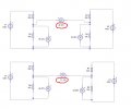
I have done a simulation of a voltage divider question from the worksheet. My question is why is the voltage different once I remove the common connecting wire. I know it something to do with the reference point not being the same, but how/where does the 71.14V comes from?
I have attached a screenshot of the simulation.
I have attached a screenshot of the simulation.
Attachments
-
 43.5 KB Views: 25

")


