Voltage divider over-voltage protection

Thread Starter

SiCEngineer

Joined May 22, 2019
443
In a voltage feedback network, where the input voltage is 300V, how can you protect against an overvoltage fault, or a fault in the high value R1 resistor?

I have de-rated the feedback resistor so that the voltage across the resistor is at most 65% less than the resistor voltage rating. I am using a 1kV 2Meg resistor for a max fault voltage of 350V. Would it be safe to assume that because resistors usually fail open, that the low voltage feedback circuitry would be safe?

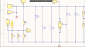
Or would I need to add something additional, such as possibly a Zener diode, in case the resistor does happen to fail short? Are there other ways better to do this? I don't want to have to worry about having issues with creepage and clearance in the low voltage circuits or where the safety ground connections are.

See image attached.

SiC
 

Attachments

Irving

Joined Jan 30, 2016
3,894
Resistors, by virtue of their construction, rarely fail short unless they flash over. Rather than use a 1kV resistor I'd use 4 x 300v 500k resistors as the risk of all 4 failing the same way is much smaller.
 

MisterBill2

Joined Jan 23, 2018
18,566
The first question is how much voltage at the output of the divider is too much? I see a 350 volt zener diode, is that to limit the maximum voltage if regulation fails? An open failure in the lower divider resistor would apply the full voltage through the R1 resistor, and so using parallel resistors in the lower section will improve reliability there.
A clamping diode on the divider output can be quite effective.
Is this for a one-off project or is it a design for a production run of many, where the cost is critical?
 

Irving

Joined Jan 30, 2016
3,894
A clamping diode on the divider output can be quite effective.
Agreed in many cases, though most modern IC have clamping diodes to + & - rails so all that is needed is a series resistor into the input to limit current into the pin. However, here I think its probably safe without. The output of the divider is around 2.8v, using 3 x 48.7k resistors in parallel. If one should fail open the FB volts rises to 4.2v which is unlikely to be damaging, especially as it will have the immediate effect of pushing the output volts down. That's likely to be lower than the controller supply voltage so Vcc clamping is unlikely, but even if it did clamp the effective source impedance of approx 24k limits the current to <200uA. Even if all 3 went open, the current would be limited to <250uA assuming a Vcc of 15v or less...
 

Thread Starter

SiCEngineer

Joined May 22, 2019
443
The first question is how much voltage at the output of the divider is too much? I see a 350 volt zener diode, is that to limit the maximum voltage if regulation fails? An open failure in the lower divider resistor would apply the full voltage through the R1 resistor, and so using parallel resistors in the lower section will improve reliability there.
A clamping diode on the divider output can be quite effective.
Is this for a one-off project or is it a design for a production run of many, where the cost is critical?
I am a PhD student, so this probably is a one-off design. ADuM4190 (Rev. 0) (mouser.co.uk) Here is the data sheet of the IC I am using. The purpose is for1) monitoring the input voltage for faults, and also 2) for input voltage feedforward in the control scheme (optional). The 350VDC is there to limit the input voltage, but also I want to stop the FET's switching when a fault is triggered.
As of now I do not have an input series resistor to the IC but this is a good suggestion - although, would this not change the voltage at the feedback node?

The output of the IC is given to my DSP which has a maximum input of 3.3V and has Zener clamps to limit this. The output of the ADUM has zener clamps but the input does not. The issue is more the creepage and clearance between the voltage sensing traces and my low voltage ground planes and traces which should be safe to touch, and if a fault occurs, the voltage may appear on these "safe" zones and make them unsafe.

Hope that makes sense.
 

MisterBill2

Joined Jan 23, 2018
18,566
The benefits of using a clamp diode external to the IC are that the external diode can usually handle a lot more current, and they are a lot cheaper and simpler to replace than most ICs.
But the clamping diodes do need to be used correctly, so a bit of research will be required. And along with that clamp diode, a fairly low value series resistor to limit the current and possibly serve as a fuse.
 
While I don't know the answer to your question - resistors don't fail short. They fail open.

Metal film resistors puddle. It was quite an interesting site in an audio amplifier.

The voltage divider that was used for a 15kV 1A power supply was a bunch of 620K, I believe wire-wound resistors.
They would fail open. The bigger problem was mechanically securing the electrical connections to the resistors.
 
Top