Voltage Divider help

Thread Starter

Sweetl14

Joined Oct 23, 2012
4
My electrotechnology study group is having trouble with one of the questions we are studying for on our upcoming exam. Here is the question: Design a voltage divider to supply 10V at 10mA and 25V at 25 mA from a 40V DC supply with a bleeder resistor current of 10mA. We have found the resistance of Rb of 1000ohms, we have also found the Pb of 0.10 watts. We are not sure what the question is asking for. Any help would be greatly appreciated.

Thanks
Lori
 
Last edited by a moderator:

wmodavis

Joined Oct 23, 2010
739
My electrotechnology study group is having trouble with one of the questions we are studying for on our upcoming exam. Here is the question:Design a voltage divider to supply 10V at 10mA and 25V at 25 mA from a 40V DC supply with a bleeder resistor current of 10mA. We have found the resistance of Rb of 1000ohms, we have also found the Pb of 0.10 watts. We are not sure what the question is asking for. Any help would be greatly appreciated.
Thanks
Lori

I think you need to show your work for what you have so far determined. A schematic would be essential. Show applied voltage and all specified currents and resistances and your calculations. Other wise we do not know where you are on the understanding of the problem. We of course could guess and assume but may mostly waste your time.
 

absf

Joined Dec 29, 2010
1,968
My electrotechnology study group is having trouble with one of the questions we are studying for on our upcoming exam. Here is the question: Design a voltage divider to supply 10V at 10mA and 25V at 25 mA from a 40V DC supply with a bleeder resistor current of 10mA. We have found the resistance of Rb of 1000ohms, we have also found the Pb of 0.10 watts. We are not sure what the question is asking for. Any help would be greatly appreciated.

Thanks
Lori
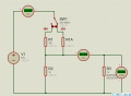
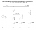
I am not sure I understand your question correctly. Is a bleeder resistor same as a "load resistor"? This is how I would do it for the 10V 10mA part. As for the 25V 25mA, you'll have to figure it out yourself..... Hint - [R1 resistance]

Allen
 

Attachments

WBahn

Joined Mar 31, 2012
33,184
I don't think that is the circuit the OP is working with (but it could be -- the OP really needs to provide more information). The best guess I could come up with is that the circuit is supposed to have two Vout taps - one that draws off 20mA while at 25V and one that draws off 10mA while at 10V. So I envision a three resistor series chain with the bleed resistor being the bottom resistor.

Of course, this is a pretty lousy circuit for any practical purpose, but it isn't too bad from the standpoint of getting people that have just learned the typical two-resistor divider to general the concept a bit.
 

absf

Joined Dec 29, 2010
1,968
I thought so as the question was not clearly spelt out. I have to make some assumptions for the OP to clarify if that is what he wanted or NOT....

Actually my guessed circuit was attached as below.

Allen
 

Attachments

JoeJester

Joined Apr 26, 2005
4,390
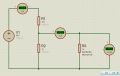
This is the circuit per the OPs description. I purposely didn't display the resistance values so the OP can use KCL and KVL to figure out those values.

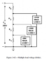
Also attached is a typical voltage divider used many years ago and still exists in the NEETS modules, Module 1, Chapter 3.
 

Attachments

Last edited:

WBahn

Joined Mar 31, 2012
33,184
This is the circuit per the OPs description. I purposely didn't display the resistance values so the OP can use KCL and KVL to figure out those values.

Also attached is a typical voltage divider used many years ago and still exists in the NEETS modules, Module 1, Chapter 3.
I don't know that this is the only circuit that would meet the OP's description, but it is identical to the circuit that came to my mind (described above).

@Lori:

If this is the circuit that you are working with, consider the following questions (using JoeJester's first diagram):

Q1) What is the current flowing in R2 (remember, you know the current flowing in the bleeder resistor and the 10V load)?
Q2) What is the voltage that appears across R2?
Q3) What is the value of R2?

Now repeat the above process for R1.

Q4) What is the current flowing in R1 (remember, you know the current flowing in R2the bleeder resistor and 25V load)?
Q5) What is the voltage that appears across R1?
Q6) What is the value of R1?

Answer as many as you can, in order, as best you can and we will proceed from there.
 
Last edited:

WBahn

Joined Mar 31, 2012
33,184
No. The bleeder is not the same as the "load".

http://en.wikipedia.org/wiki/Bleeder_resistor
And I normally wouldn't think of the bottom resistor in a voltage divider as a "bleeder", either. But referring to that resistor was the only choice that made any sense. I don't know if any common name applies to either resistor in a voltage divider. I think I could make a case for calling it a ballast resistor, but it would be a pretty weak case and draw upon a more general notion of the term ballast than is usually used in electronics.

Actually, just thinking about it some more, I guess I can see how that resistor would (or at least could) act as a bleed resistor for the load, so perhaps that's not a bad name for it after all.
 
Top