voltage controlled sinusoidal oscillator 0 - 100 Hz

Thread Starter

onlyvinod56

Joined Oct 14, 2008
369
Hi every one,
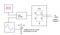
i'm working over a pwm based inverter. The main objective of the inverter is that can generate a wide range of frequencies with a fixed terminal voltage (230v).
So, i need a reference sinusoidal voltage. Can anybody give me a schematic of an oscillator whose frequency is controlled by a voltage.
thanQ
 

eblc1388

Joined Nov 28, 2008
1,542
Be realistic. No oscillator can generate 0Hz.

Voltage control? What control voltage ranges? 0~5V, 0~30V?

How good(i.e. low distortion) you would want the sine waveform to be?

5%, 1% , 0.1% or 0.001% distortion?
 

Thread Starter

onlyvinod56

Joined Oct 14, 2008
369
Be realistic. No oscillator can generate 0Hz.

Voltage control? What control voltage ranges? 0~5V, 0~30V?

How good(i.e. low distortion) you would want the sine waveform to be?

5%, 1% , 0.1% or 0.001% distortion?

Ok. Let the frequency range be 1 - 100Hz and the control voltge be 0 - 10v. I need the maximum possible exact sinusoidal.
 

Thread Starter

onlyvinod56

Joined Oct 14, 2008
369
Why don't you use the microcontroller to produce the sine wave you want.
Sorry, mik3.
In my project i dont want to use any programmable controllers. That too for a sample sinusoidal, i think its not necessary.
anyways, if its not possible with analog ICs, then i will go for microcontroller.
 

Thread Starter

onlyvinod56

Joined Oct 14, 2008
369
Hello,

It sounds perhaps strange, but take a look at some VCO's of this website from "Music From Outer Space"
http://www.musicfromouterspace.com/analogsynth.php?page=ANALOG
There are VCO's that will work over 8 octaves. (look at the VCLFO).
You will NOT go down to 0 hz but pretty low.
http://www.musicfromouterspace.com/analogsynth/AAA_OscillatorIndex.php?page=ANALOG

Greetings,
Bertus
ThanQ
but the circuits seems to be big and complicated.
can i get from basic wein bridge or colpitts oscillators......(any basic oscillator)?
keep the distortion aside.
i'll send an attachment in the next reply. just check it
 

Thread Starter

onlyvinod56

Joined Oct 14, 2008
369
If you search in google for sine wave oscillators you get lots of results. Here are some:

http://www.national.com/ms/LB/LB-16.pdf

http://www.national.com/nationaledge/jun04/article.html

http://hobby_elec.piclist.com/e_ckt18.htm

The frequency is controlled by a variable resistor.
How can i replace the pots. it is not manual control. Its an automatic system where the frequency is decided by the system itself. the decision will be a dc voltage that must be given to this voltage controlled oscill
 

Attachments

Wendy

Joined Mar 24, 2008
23,415
ThanQ
but the circuits seems to be big and complicated.
can i get from basic wein bridge or colpitts oscillators......(any basic oscillator)?
keep the distortion aside.
i'll send an attachment in the next reply. just check it

You can't have it both ways, a sine wave VCO is complicated. I doubt you'll be able to use either a Wein Bridge or a Colpitts in that frequency range. It can be done at RF frequencys because the LC networks are so small, which lends itself to small adjustments making big differences.

If you don't want to use a microcontroller you may still have to go digital. It is possible to generate reasonable sine waves using DAC convertors, though they will have harmonics.

What are you using it for? It might help people figure out a resonable compromise. Does the voltage control have to be linear?
 

bertus

Joined Apr 5, 2008
22,270
Hello,

An other idea is frequency beating.
There is a fixed oscilator and a variable oscillator.
These can be both LC oscillators, one fixed and one tuned with a varicap.
Both signals go on a mixer circuit.
The difference signal will come out of the mixer circuit.

Greetings,
Bertus
 

Wendy

Joined Mar 24, 2008
23,415
That could work, it would be mediocre complex and require a lot of tweaking. I've never heard of a power frequency lower than 50Hz, but I have heard of them up to 400Hz. I still wonder what the OP is trying to accomplish. Inverter implies transformers, and finding transformers over that big a range is pretty unlikely.

I'm still stuck mentally on a Digital to Analog technique. The problem is you don't want too many steps in the digital, since it multiplies the oscillator frequency correspondingly.
 

bertus

Joined Apr 5, 2008
22,270
Hello,

The pureness of the sine depends on the number of steps you take for it.
You could use a "smoothing" filter circuit behind it.

Greetings,
Bertus
 

Wendy

Joined Mar 24, 2008
23,415
I know, but like I said, the more steps, the higher freq the base VCO has to be, and the wider range it has to cover. Anything that smoothes the waveform out also affects frequency response, which might not be a big deal. I've seen them out there, I was thinking of a 4017 based version for that output.
 

bertus

Joined Apr 5, 2008
22,270
Hello,

You only have to create a "table" for 0 - 90 degrees.
1) count up ( 0 - 90 )
2) count down ( 90 - 180 )
3) invert signal, count up ( 180 - 270 )
4) invert signal, count down ( 270 - 360 = 0 )

This saves you a lot of points.

Greetings,
Bertus
 

Wendy

Joined Mar 24, 2008
23,415
The core problem is always number of counts for the clock. That and the 4017 only "counts" in one direction. I thought of using ROM or some analog, but I'm keeping it simple.
 

bertus

Joined Apr 5, 2008
22,270
Hello,

You can also make 0 - 180 with the 4017.
Invert the signal and do it again for the 180 -360.
This leaves you 10 steps for 180 degrees.

Greetings,
Bertus
 
Top