Facebook
 Google
 GitHub
 Linkedin
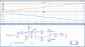
Hi gents, I am a total amateur when it comes to electronics but need a voltage controlled current source signal conditioner.
Input +/- 10V with linear
Output +/- 50mA ( the impedance of the driven input is max. 10Ohm)
what OP amp product would you use and what would the circuit look like.
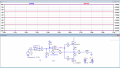
Input +/- 10V with linear
Output +/- 50mA ( the impedance of the driven input is max. 10Ohm)
what OP amp product would you use and what would the circuit look like.