Voltage controlled Clipper?

Thread Starter

liquidair

Joined Oct 1, 2009
192
Hi All,
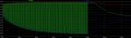
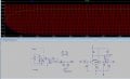
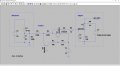
I'm trying to design a voltage controlled clipper circuit. I've got something that almost works. It takes a positive voltage, creates a negative voltage in proportion to the control voltage, and clips the incoming signal. The circuit tracks wonderfully if the control voltage is much larger than the signal, but as the signal grows, it interferes with the tracker circuit so the proportion gets way off. I've tried a lot of ways to isolate the two, but everything seems to cause the circuit to no longer work (in the attachment, D2, R9, and C2 are all attempts at this).

A further wrinkle is that I want to do the same sort of thing, but instead use a negative control voltage to generate a negative proportional envelope (say 1.7-2x), and hopefully switch between the two versions.

Is there a simple/elegant solution? Is there a better way?

Ideally, what I'm looking for would act as a variable zener diode. I've also tried adjustable zener circuits but those don't seem to work well with AC signals (won't clip like a zener or biased diode would, and don't seem to be able to be configured to work negatively).

Thank you all for taking a look!
 

Attachments

crutschow

Joined Mar 14, 2008
34,432
Here's the LTspice simulation of an accurate plus and minus clamp using a quad op amp, that works down to 0V.
V2 (red trace) determines the plus clamp voltage and V5 (green trace) determines the minus clamp voltage of the output (blue trace).
Does that do what you want?

upload_2019-10-16_20-7-11.png
 

Thread Starter

liquidair

Joined Oct 1, 2009
192
Hi crutschow! Almost; I can't use opamps because the voltages are too high (could be >100v). However, I saw a very similar circuit that looked like it had promise if we could replace the opamp with something discrete like a diff amp and the positive input would track its cv precisely.

This looks like the opamp replacement would also allow us to easily switch to the negative cv; we could just add gain. I think?
 

crutschow

Joined Mar 14, 2008
34,432
If you explain exactly the nature and source of the signal you want to clip, we may be able to offer better solutions.
Is it plus and minus 100V or 0V to 100V?
What power supplies do you have available?
This looks like the opamp replacement would also allow us to easily switch to the negative cv; we could just add gain. I think?
I don't understand what signal you want to add gain to. :confused:
 

Thread Starter

liquidair

Joined Oct 1, 2009
192
If you explain exactly the nature and source of the signal you want to clip, we may be able to offer better solutions.
Is it plus and minus 100V or 0V to 100V?
It's audio so it can be anywhere in between +/- 100V.

What power supplies do you have available?
A high voltage supply of ~400V, +33V, +12V and a negative supply of about -75V.

I don't understand what signal you want to add gain to. :confused:
Lol, ya sorry, I got excited that your suggestion may work and left out details!

The first attachment is the desired result from when my original circuit is working properly. The green is obviously the audio, and the red is the sidechain signal (I simulated that with a DC supply even though it will be based on the rectified and smoothed audio). The blue is the clipping envelope based on the (inverted) sidechain signal...it almost perfectly and smoothly tracks the red, just negatively.

The 2nd attachment shows the problem. The signal follows the sidechain on top just fine, but because the negative signal can still swing fully negative entering the clipper, it adds itself to tracking envelope and thus it no longer sticks with the red, just opposite.

What I was talking about with gain is for a second circuit I need that will essentially take the blue envelope signal and create another negative envelope but 1.7-2x more negative. So if the opamps could do this, then I figured for that version, all we'd have to do is give it a gain of 1.7-2x and feed it the blue signal, and we'd get the desired signal there.

I hope that explains it better!
 

Attachments

Thread Starter

liquidair

Joined Oct 1, 2009
192
So crutschow, you were right the first time. I think we've got something that will work using a simple discrete opamp...see attached.

I'm outside of my comfort zone here though, so there's some things I'm struggling with:
1. Is there a way to reduce the opamp currents? It's looking like I'll have to idle that puppy at 35mA or so. I would think that we should be able to adjust things to get that much, much lower as this shouldn't be a heavy job for the opamp.

2. Is there a simpler circuit to use here, maybe just a diff amp or something?

3. I can adjust the gain and follow the envelope signal pretty close, but is there a way to clamp it so that it's always a minimum X volts away (just inverted)? So for instance, if our input was 40V we would get -45V output, and if our input was 30V our output would be -35V. It looks like it tracks OK but as the input voltage gets lower the output gets a little too close at times.
 

Attachments

Top