It's very difficult to read your schematic, but it would appear the your receiver side is not set up to run on a single supply. Try you simulation with a simple sine wave and see what it looks like coming out.
It's very difficult to read your schematic, but it would appear the your receiver side is not set up to run on a single supply. Try you simulation with a simple sine wave and see what it looks like coming out.
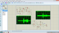
Actually I tried this circuit on breadboard and it worked. I built this circuit using LASER light as communication channel and using analog modulation of voice signal. Here's the schematic.
Actually I tried this circuit on breadboard and it worked. I built this circuit using LASER light as communication channel and using analog modulation of voice signal. Here's the schematic.
Well, If your happy, I'm happy.
But I will ask just a couple of questions.
What is the purpose of RV2/R6?
Since there is no input resistor, what is the purpose of R7.
Since the speaker is connected to ground and the lm358 has no negative supply. How can the speaker ever see a voltage below ground?
@Rejan Chitrakar
Is there a question here?
Please re-read the TOS/UA. You are NOT allowed to use the forums to promote your advertisement-based YouTube channel. This thread will be locked.
Post another and you are history.
 Facebook
 Google
 GitHub
 Linkedin
")


