Found it is on-line edition only. That creates kind of a dependence I don't feel at ease with.For publication quality schematics I use Scheme-it at Digikey.
Last edited:
Found it is on-line edition only. That creates kind of a dependence I don't feel at ease with.For publication quality schematics I use Scheme-it at Digikey.
Oh that's great. Do you use a different schem editor when you have to do a simulation in LT Spice?What makes you say that?
I like LTSpice as a simulator, just not as a schematic editor.
Only when I need to modify the schematic to make it understandable by non sim users.Oh that's great. Do you use a different schem editor when you have to do a simulation in LT Spice?
I should mention that I do not like any schematic editors because they are so picky about where you place objects and how they connect. You have to constantly push things around sometimes to get it to look right. It takes significant effort.Only when I need to modify the schematic to make it understandable by non sim users.
I feel the same way about schematic editors. That's why I'm still using Visio for schematics and circuit boards. It gives me the freedom to draw what I want, where I want it, and to re-scale any part or the whole thing. Over the years I have built up a library of basic electronic components. The version I am using is 32 bit. I copied it from twelve 3 1/2" floppies onto a CD and ran it in XP for many years. Recently I copied the whole file to a Win 8.1 computer and it runs in emulation mode.I should mention that I do not like any schematic editors because they are so picky about where you place objects and how they connect. You have to constantly push things around sometimes to get it to look right. It takes significant effort.
When doing a hand drawing, unless it is a very complicated schematic, you can draw it up pretty quick even with lots of notes and component values and enumerations.
etc..............................................

Hola @MrAlI should mention that I do not like any schematic editors because they are so picky about where you place objects and how they connect. You have to constantly push things around sometimes to get it to look right. It takes significant effort.
When doing a hand drawing, unless it is a very complicated schematic, you can draw it up pretty quick even with lots of notes and component values and enumerations.
This led me to think about a program that can take a hand drawing and convert it into a nice, neat schematic, even if it has limitations for some things. This would be a monumental task though so I doubt I will attempt it, at least for now. I've done some other symbol recognition programs, but they involved fairly straight lines and rectangles and such so much easier. The software logic just has to follow the graphical lines to figure out what is what.
Maybe I'll give it some more thought, but it would probably take up too much time for me right now.
This isn't that funny but it seems comical just the same. I could see it now that the program would have to do things like: "Find something that looks like a resistor", "Find something that looks like a diode", "...something that looks like a transistor", etc., etc. (ha ha).
Probably also require 'training' like an ai program. I found that kind of thing way too boring to do for me.
Hi,I feel the same way about schematic editors. That's why I'm still using Visio for schematics and circuit boards. It gives me the freedom to draw what I want, where I want it, and to re-scale any part or the whole thing. Over the years I have built up a library of basic electronic components. The version I am using is 32 bit. I copied it from twelve 3 1/2" floppies onto a CD and ran it in XP for many years. Recently I copied the whole file to a Win 8.1 computer and it runs in emulation mode.
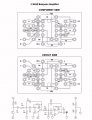
View attachment 324039
The circuit is part of a smoke detector system I built. The result of me attending many heavy metal rock concerts in the 80s and 90s have resulted in a serious loss of hearing for me for the last few years. Even when I am using my hearing aids, I can not hear anything above about 2.5KHz. That includes the 3.3KHz tone from our smoke detectors. It makes cooking much easier but presents some obvious problems. At night, when I am sleeping, I don't use my hearing aids.Hi,
I took a quick look at your schematic (didn't check out the boards though) and I saw immediately that it was a very unusual design. The reason being that the op amp non inverting terminals are biased with two 10k resistors from a DC source, which is typical, but also that the two lower resistors (330 and 270) are also biased by the same two resistors.
This leads to an unusual interaction between the first and second stages. Since the ratio of the near 300 Ohm resistors and the two 10k resistors (5k in parallel) is very low, that means the near 300 Ohm value resistors have no problem modulating the bias junction between the two 10k resistors. Thus, the point of interaction is at the junction between the two 10k resistors.
Now lowering their values to 1k there would be much less interaction, and lowering them to 100 Ohms each there would be even less interaction. This would lead to a sharper response and a more typical operation.
Of course a sharp response is not always desirable, but broadbanding a bandpass filter usually isn't done that way. Each stage could be designed with a broader response to begin with.
There is also the possibility of battery operation, in which case two 10k resistors would draw less current than two 1k resistors.
What I would have to wonder about is what this is going to be used for, and was the broadband design done on purpose or by accident.
Also it looks like the center frequency is higher by close to 1kHz. Not sure if that was intentional or not either.
Hi,The circuit is part of a smoke detector system I built. The result of me attending many heavy metal rock concerts in the 80s and 90s have resulted in a serious loss of hearing for me for the last few years. Even when I am using my hearing aids, I can not hear anything above about 2.5KHz. That includes the 3.3KHz tone from our smoke detectors. It makes cooking much easier but presents some obvious problems. At night, when I am sleeping, I don't use my hearing aids.
I designed my smoke alarm to detect the 3.3KHz tone from the ceiling smoke detectors. This is amplified and connected to a Bluetooth audio transmitter. The output of a remote, paired Bluetooth receiver is detected and turns on a very loud, raucous audio tone which I am able to hear without my hearing aids.
In the diagram, I omitted the 10uF capacitors connected between ground and the positive and negative supply rails which I added to the circuit after the first test. The circuit works very well. The bandpass filter is narrow enough to eliminate other high frequency noises like running water, etc.
Each unit is powered by a 10V wallwart. A 9V battery in each is connected to the supply through a diode to keep the units running during a power failure.
| Thread starter | Similar threads | Forum | Replies | Date |
|---|---|---|---|---|
|
|
Visio 2021 for $9.99 | Marketplace | 4 |
| Similar threads |
|---|
| Visio 2021 for $9.99 |