Facebook
 Google
 GitHub
 Linkedin
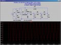
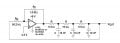
It was suggested by someone on this forum that I built a phase shift oscillator since I was having trouble with my colpitt. I would like to make the one below, but from a single 9v battery supply. My problem (so far) is I'm not sure how to make that 2.5v at the Vin. I tried a voltage divider, but wasn't sure that was right because if it's a virtual ground it really doesn't go to ground?
Mistake: that op-amp in the picture is the LM358 (I've been making too many searches on the atmega385") )
)
Mistake: that op-amp in the picture is the LM358 (I've been making too many searches on the atmega385
)Attachments
-
 34.5 KB Views: 83
Last edited: