Facebook
 Google
 GitHub
 Linkedin
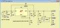
I am building a simple power supply using a wall-wart. It supplies a little over 16 volts output with a max 650ma draw. I am entertaining the idea of adding this voltage divider (virtual ground) in the power supply. I bought the wall-wart for a dollar from goodwill. This is all being built on the cheap side. I'm not buying a lm337 or a virtual ground IC. Thoughts?

1. Should I add a diode?
2. Are 100KΩ resistors too much/too little?
3. Is this going to be a problem?
1. Should I add a diode?
2. Are 100KΩ resistors too much/too little?
3. Is this going to be a problem?