Facebook
 Google
 GitHub
 Linkedin
Hey Guys,
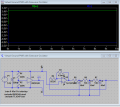
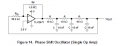
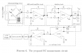
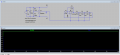
I am a recent grad student and really want to build an analog EC meter for a summer project I am working on. I have a good foundation on basic circuitry and arduino interfaces but when it comes to Virtual grounds and power rails I get really lost. The EC schematic I am working off of (link below / img 2) demands for a 5kHz sine wave oscillator. I was thinking about using the single op amp phase shift oscillator (img 1) which uses a TLV2471 op amp and three RC cells. Following that the EC meter schematic uses four LF351 op amps (img 2). After sifting threw the forms I found this article explaining virtual ground circuits pretty well (link 1), I dont really know which one to use. I was thinking of going with the buffered based virtual ground driver utilizing BUF624 (img 3) due to the fact that it can handle voltage offset pretty well as long as the power draw on this circuit is evenly balanced... this is were I get mixed up, again my circuitry knowledge is limited. I guess what I am asking is what is a practical way to properly power the TLV2471 and the four LF351 op amps. I have been using LTspice, which has been fun but even when I am just implementing the single op amp phase shift oscillator and the power supply the power is not evenly drawn from + and - side (img 4). If someone could point me in the right direction that would be awesome, any criticism will do, I really want this to come together and willing to barrel threw articles in order to get this done. I have been researching for a while but I think due to my lack of conceptual knowledge on circuitry I have been in a standstill.
Thanks again for reading images and links are below
Link one (http://tangentsoft.net/elec/vgrounds.html)
Attachments
-
 9.9 KB Views: 25
 -
 64.7 KB Views: 26
 -
 8.5 KB Views: 25
 -
 186.7 KB Views: 25