VFD start up help - connecting to multifunction input terminals.

Thread Starter

fiftyv8

Joined Jan 29, 2018
223
I am in the final stages of setting up a VFD which I am using to operated a bead roller machine that I have built.
I also belong to the All Metal Shaping Forum and this complete build thread can be viewed there.

http://www.allmetalshaping.com/showthread.php?t=18321

I chose a Folinn BD600 VFD unit which was based on there being a local supplier and the unit appearing most compatible with the 3 phase supply I had available to me. I have since discovered my supplier and manufacturer are far from committed to offering any tech help once the unit has been purchased.

I have attached a copy of the manual provided with my VFD purchase.

Presently, I have my machine completed mechanically and wired electrically to the point where my VFD is mounted and wired with ac power to the motor and programmed to motor parameters and I have set a speed range which I am happy with and that stuff all works.

Remembering I am not any where close to being any kind of electronics person little lone an expert so I don't speak your language mostly.
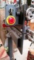
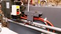
I have setup my machine with a simple single circuit to include a stop/start foot pedal, a emergency stop switch and a forward/reverse switch remotely from the VFD control box.

I have also attached a pic of this circuit, my VFD and switches location and a face view of my Folinn VFD unit which I hope will help anybody willing to assist me better by being able to visualise what I have.

Going by my simple circuit, I would like to have my previously mentioned switches operate remotely from the VFD.
I have 3 wires that I have concluded need to be connected back to the VFD multifunction panel which denoted connect points S1 thru to S6 which can be found on P15, P18 & P37 (programing) of my manual.

In my naivety, I had thought that by connecting to S1 and S6 with my common wire connected to the DCM it would result in a circuit that once programmed by S1 - F05.00 to setting 1 for forward run and S6 - F05.05 to setting 2 reverse run, once I chose to select forward or reverse via my switch dial and hit the start on my foot pedal I would see a response, but no action.
All my settings still remain operable from the face of the VFD and not remotely.

What am I doing wrong or what am I missing since I lack any electronic/programming instincts to tell where I have gone wrong...
I know I must be close but how close maybe you guys can tell me.

If I am on the wrong forum with this request please let me know.

Many thanks,

Russ.
 

Attachments

Last edited:

MaxHeadRoom

Joined Jul 18, 2013
28,618
It looks to me as though you need to set F00.01 = 1, Control from terminals, most VFD's in this configuration also disables the front panel pot.
So a 5k pot would also be needed for RPM control.
F00.05 is the frequency lower limit.
And use F00.06 = 2.
Max.
 
Last edited:

Thread Starter

fiftyv8

Joined Jan 29, 2018
223
Wow thanks, I'll give that try.
If possible I would prefer to leave the pot as it stands but if no choice, I can set up a remote pot.

Speed from the pot is generally just a one of setting as required per each task performed so not used in my case as an accelerator pedal during a single cycle.
I'll be back...
 

Thread Starter

fiftyv8

Joined Jan 29, 2018
223
Max, I set the F00.01 to 1 and yes you are correct, it did disable the panel and was asking for a "P" code (on page 23) which was flashing in the display screen, which I assume to be upper and lower limits as you eluded to.
The panel pot was also unresponsive as you anticipated.

Right now, I only have a 10k pot available to me would this work or does it need to be a 5k item???
Secondly, on page 92, which has had my attention for some time now, is this in any way related to what I have been trying to achieve with my
1 DCM + 2 wires or is it totally unrelated???

I am really thankful for your advice,

Russ.
 

MaxHeadRoom

Joined Jul 18, 2013
28,618
The 10k pot should be OK, needs to be linear variety not logarithmic.
Not sure what you are looking at on 92, did you mean the p91 value 10?
If so that is for just incrementing speed by contact push.
Also there is a feature of implementing from 1 to 16 preset speeds via the combination of 4 input selections.
Max.
 
Last edited:

MaxHeadRoom

Joined Jul 18, 2013
28,618
Do you mean the difference between 2-wire control and 3 wire, which includes the Stop button function, instead of just opening the FWD or REV?
Max.
 

Thread Starter

fiftyv8

Joined Jan 29, 2018
223
Yes, I admit to not understanding it but was wonder if it was pertinent to what I was trying to achieve or whether I was just following a wrong lead.
It seemed to me as a layman like it might have been another way of doing what I was seeking using different connect points.
However to me the connect points were not making any real sense as I could not see where they were on my unit...
 

Thread Starter

fiftyv8

Joined Jan 29, 2018
223
Just going back to what we are focusing on and forget page 91 for now.
I have installed my remote 10k potentiometer and when functioning will run the full speed range as it did using the face panel pot.
I've set the F00.06 to selection number 10
I've set F00.01 to number 1

However I have struck problems;
When fired up the unit will just run straight away and is not influenced by my 3 position forward and reverse switch, except for when that switch is turned into the RH position, lets call it forward for reverse since the shaft is rotating in the reverse direction.
The only way I can influence the motion is by pressing down the foot pedal which then stops the motion.
When the 3 position switch is in either of the other two settings the foot pedal has no effect.

The foot pedal was designed to start the rotation when pressed down, so it is doing the opposite right now.

I currently using the S2 and S6 and the DCM points for my 3 wires related the sketch circuit I posted earlier.
 

Thread Starter

fiftyv8

Joined Jan 29, 2018
223
There is obviously something going on that the VFD does not seem to like.
I ended up resetting back to factory defaults and reinstalled my motor parameters which had mainly held and then after numerous attempts have tried to select my speed upper and lower limits.

So far I have only been able to get the VFD to accept the upper of 120hz, but it will not function at my lower limit of 20hz yet it is set but continues to run down to zero hz, which is not what I want or feel is good.

I am just wondering if I might be better off setting my foot pedal as a 3 wire stop/run momentary style separately into the VFD and then find a way to then connect up my remote fwd/rev switch on a another set of S connect points.
Does this sound do-able???
 

Thread Starter

fiftyv8

Joined Jan 29, 2018
223
motor parameters are;
volts 415
amps 1.05
kW 0.37
rpm 1365
Hz 50

Require VFD to offer a max speed of 120hz
Upper speed limit 120hz
Lower speed limit 20hz
Which initially it has been capable of delivering.

I seek in addition to run a remote emergency stop button, fwd/rev switch which included a centre off position
I have come to realise that the VFD panel for fwd/rev has no off position it just changes direction automatically.
Finally I have a foot pedal that can be run as a momentary stop/start switch (3 wires) or using 2 wires as a run switch when held down continuously.
 

MaxHeadRoom

Joined Jul 18, 2013
28,618
But as I previously asked, what are you parameters set to for external control?
The panel FWD/REV Will automatically go from one to the other unless Stop is pushed.
Do you want a reverse feature with a foot pedal??
Parameters F00.00?
F00.01?
F00.05?
F00.06?
F05.00?
F05.05?
F08.14?
Max.
 

Thread Starter

fiftyv8

Joined Jan 29, 2018
223
My current settings for the Parameters you note are as follows;
F00.00 = 0 default
F00.01 = 0 but was 1 as suggested by you but I returned it to 0 when things went wrong.
F00.05 = 20hz but when using panel pot the speed still drops all the way down to zero.
initially before contacting the forum for help and making changes, it was holding at 20hz.
It still reads 20hz in the program.
F00.06 = 10
F05.00 = 1
F05.05 = 0
F08.14 = 0

Max, my humble apologies with respect to the past page reference of page 92 it should have been page 96.
Sorry, dealing with this as a layman is doing my head in...
I am obviously in a different time zone to you so that kinder slows things down a little.

Many thanks,

Russ.
 

MaxHeadRoom

Joined Jul 18, 2013
28,618
I would think that the parameters for pot input and command on S1 & S6 (any reason for S6 and not S2?) two wire control and pot on AI1.

F00.00 = 0
F00.01 = 1
F00.05 = 20hz
F00.06 = 2
F05.00 = 1
F05.05 = 2
F08.14 = 2
Fig 6-9 p96 configuration.

F02.02 set for 50hz or 60hz (motor dependent)
F02.03 set for motor plate rpm.
Max.
 

Thread Starter

fiftyv8

Joined Jan 29, 2018
223
Max, F02.02 & F02.03 are set correctly.
S2 at the time of me attempting settings before contacting the forum would not accept the number I tried to key in.
So I then selected S1 which did.
I believe if my memory serves me correctly I initially chose these numbers after looking at a YouTube video for installing remote attachments and just followed his number choice. I realised that my unit was a different brand but it would seem many follow similar numbers after looking at numerous YouTube videos for initial understanding of how to get started.

I have just installed all the above numbers into the F codes as you offered, all were accepted with the exception of F05.05 which will not offer a choice of #2, only 0, 3,4,etc, so I left it on 0.

After installing all the numbers stated above, I note the following when the unit is turned ON.
The top row of panel lights display shows RUN and REV lit up.
Panel RUN button will not start motor.
Motor is started by rotating my remote 3 position fwd/rev switch from the center OFF position to the right, but when turned back to the center OFF position the motor will not Stop.
The motor is stopped by hitting the panel STOP button.

The motor only runs in the reverse rotation and can not be reversed by hitting the panel FWD/REV button.
The remote Pot is not functioning and motor speed is only influenced by the panel Pot, but motor speed bares not relationship to speed selected and if maximum 120hz is dialled the motors seems to stall, if turned down slightly it wants to JOG, yet at about 65hz on the display the motor will run continuously, but probably not at the true speed of 65hz in my estimation.
 

MaxHeadRoom

Joined Jul 18, 2013
28,618
I have configured quite a few different makes of VFD's, including the Chinese versions and have not seen such a problem of simple config settings?
I assume there is little or no factory support?
Max.
 
I have a comment not related to the local discussion, but an Emergency Stop circuit should cut the mains. Your on your own to provide that.

So, there is a difference between stop and E-stop/
 

Thread Starter

fiftyv8

Joined Jan 29, 2018
223
Max, yes you are correct no support from the factory of any substance.
I was surprised the only YouTube video they have is of somebody walking thru the factory carpark and into the front office.
As time passes, I in all honesty could not advise anybody to consider purchasing this brand of VFD compared what I have over time discovered about how much help and information there is out there for some other brands.

KISS, yes you are 100% correct in technical terms, but since being homemade there are few requirements or controls to provide any type of stop switches, so I just decided to at least have a minimum level of safety stop provisions rather than none at all.

I figured that the E stop type switch at least was high visibility and in a prominent position for the uninitiated compared to the panel STOP switch which is small and I figured it may stop working once other remote controls are added.
I also have a main power ON/OFF switch which is prominent from the back of the machine and is in a strategic position also.
I expect that I will be the only person using this machine but was also concerned about the chains and sprockets being exposed and hence the guards.
I note most I've seen on the internet have no guards or special stop switches so I have just done what I thought would be better than nothing.
The other thing that still is a concern is the run on factor that even when power is cut there is still some inertia in the drive so there is no dead stop anyway.
 

Thread Starter

fiftyv8

Joined Jan 29, 2018
223
OK folks, we are back in the game.
I sat down and went thru every possible F code that I had been interested in and worked my way thru them all to determine that they either had a default number in them or alternatively a number as suggested by Max.

I discovered that connect point S7 (which is not being used) had a 2 instead of default 0 and then S6 would accept my number 2 selection.
What this has done now is amazing, as I have full function in my remote Pot, and similarly in my remote fwd/rev switch and so called E switch.
My foot pedal functions when pressed down as the RUN function and that is all I had asked from you guys.

So we are in front now, with the exception that my speed control is not working right.
If I dial speed in upto approx 90hz the motor runs as expected, however once over the 90hz point it kinder stalls and wants to jog, when I remove my foot from the pedal during this JOG process the motor runs free for a second or two and then stops as commanded.
It is weird to say the least.
Similarly, the lower limit of 20hz is not respected when dialling down, it still goes right down to zero speed which it is not required to do with the lower limit I have set.
Any ideas men.
I am just asking as a layman again and wondering if by changing F05.01 selection from 4 to 0 would that be OK, or are there any other F codes that are not in use that I could be selecting that will totally ensure they are having no effect upon my other active choices???

We are damn close now...
 
Top