Varying phone draw current. Wall charger vs hand cranked charger.

Thread Starter

tomydom

Joined Dec 7, 2016
32
I'm trying to determine what the problem is here. Explanation below.

When I plug my phone into a wall charger (USB output) I measure the output voltage as being 5.2 volts with a draw current of 1.5 Amps (the phone draws 1.5 Amps). That's pretty constant.

I have a hand cranked charger which will charge at 5.5 volts and allow a draw current up to 3 Amps. So I tested it by placing a load on the charger and sure enough when this loading device is set to draw 3 Amps it can draw 3 Amps consistently. So the hand cranked charger works as it should, without issues.

But...... When I connect this hand cranked charger up to my phone, the draw current varies wildly (no doubt due to the variations in hand turning speed as I turn the crank handle). It will quiet easily output 5.5 volts without much variation, but the draw current is only around .5 to .6 of an Amp. Remember this device will output up to 3 Amps at this voltage (as my test showed). Also, as mentioned, when the wall charger is used, the phone draws about 1.5 Amps.

My question is, why won't the phone draw 1.5 Amps when I'm charging with the hand cranked charger? Could it be to do with the charging module in the phone, the USB connectors used from the hand cranked charger, or something else?

Thanks.
 

wayneh

Joined Sep 9, 2010
18,135
The higher current draw is enabled by the phone negotiating with the charger. It sounds like your hand cranked one does not respond to a query from the phone and thus the phone assumes it’s a dumb, lower current charger.
 

Thread Starter

tomydom

Joined Dec 7, 2016
32
The higher current draw is enabled by the phone negotiating with the charger. It sounds like your hand cranked one does not respond to a query from the phone and thus the phone assumes it’s a dumb, lower current charger.
Thanks for replying.

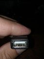
Could that be due to the USB cable coming from the charger? Once side is fixed into the voltage selector and the other is a female USB connector. The attached photo doesn't really show anything but that is the female connector. There are 4 contacts inside the female plug.


If this is is the case, then can I add something in between this USB connector and the phone so the charger will appear to respond as it should?

IMG_20180221_133055-min.jpg
 

Dodgydave

Joined Jun 22, 2012
11,395
The phone dictates the charging current , the 4 pins are 5V+/-, (with the other two as high or low current setting for Iphones only!! )
Android only need two wires, it sounds to me like the phone needs a Constant Steady voltage , try putting a 1000uF to 4700uF capacitor across the output of your hand charger.
 

Thread Starter

tomydom

Joined Dec 7, 2016
32
The phone dictates the charging current , the 4 pins are 5V+/-, (with the other two as high or low current setting for Iphones only!! )
Android only need two wires, it sounds to me like the phone needs a Constant Steady voltage , try putting a 1000uF to 4700uF capacitor across the output of your hand charger.
Thanks for that tip..

So what do I do here? Do I bridge the positive lead with this capacitor?

I'm assuming the capacitor will hold current back and release at a more constant rate.
If not, what does this do exactly?
Do I bridge the positive and negative wires with the capacitor?

Thanks.
 
Last edited:

waker

Joined Feb 21, 2018
12
At first, the action of the cracking seems to be fun. The handle is easy to use, a light will green knows that you're producing power, and your phone, sure enough, the charge is exposed. But if you hold the phone, your hand will gradually become increasingly intense.

MOD:

Please help the TS to solve his problem, stay on Topic.
E
 
Last edited by a moderator:

wayneh

Joined Sep 9, 2010
18,135
You might be able to satisfy the phone by applying specific voltages to the two data pins in the middle. This is accomplished by setting up a resistor voltage divider between the the two power rails.

You’ll have better luck if you search for the needs of your specific phone. Hopefully someone before you has done the experiments to figure it out.

I’m not 100% sure that this will enable high-current charging. It works to allow charging (versus no charging) on many phones. It’s not just iPhones that can be fooled this way.
 

Dodgydave

Joined Jun 22, 2012
11,395
Thanks for that tip..

So what do I do here? Do I bridge the positive lead with this capacitor?

I'm assuming the capacitor will hold current back and release at a more constant rate.
If not, what does this do exactly?
Do I bridge the positive and negative wires with the capacitor?

Thanks.
YES , just put the capacitor across the pos/neg pins.
 

wayneh

Joined Sep 9, 2010
18,135
What does this do?
It might carry you through brief transients in output power from the crank. This is more relevant to dropouts, since there should? be no voltage spikes coming through. I doubt it will make much difference, but it's worth a try if you notice the phone acting squirrelly as it thinks it is connecting and disconnecting.
 

BR-549

Joined Sep 22, 2013
4,928
This is funny. You had better be in good shape. You're about to learn what 10 watts of power are.

It doesn't sound like much....until you require your body to continuously produce it.

Consider ambient light panels or solar.....or a water wheel.
 

Thread Starter

tomydom

Joined Dec 7, 2016
32
Here's what I was looking for.
I think a resistor must go in here but I believe he's eluding to the same principle.


Thread Starter

tomydom

Joined Dec 7, 2016
32
Here's an article on this also.
http://blog.curioussystem.com/2010/08/the-dirty-truth-about-usb-device-charging/

It's about the different charging standards between China and Europe.
Shorting the lines doesn't seem to work for me. I'm probably better charging a power bank and charging the phone off that.

I'm yet to try bridging the two data lines with a variable resistor to see if i can find the sweet spot.

I still think that the problem with using a hand cranked generator, as mentioned above, is due to the variance in current output so the phone reverts back to the half amp i'm getting.
-----------------------------------------

Just adding a late edit to this. I've just discovered that the phone I'm using requires the European standard when charging via USB.. So that would explain why just bridging the data lines hasn't worked for me.

It's a chinese made phone so I suppose the use of the chinese or European standard depends on which market they are trying to target.. According to the article above, a 200 ohm resistor is what I need to bridge the two data lines.
 
Last edited:

Thread Starter

tomydom

Joined Dec 7, 2016
32
I just wanted to re-open this discussion because I'm still not satisfied I have resolved this issue!
Adding to the discussion above I ended up finding this web page describing the different configurations for charging via USB.
http://obddiag.net/usb-power.html
It's quiet useful, but the problem I have is that I am using a Chinese phone and it isn't responding to the bridged data lines, the resistance between data lines, or applying a 1.2v current to the data lines. There is a TP2514 IC which covers all these configurations (including apple's USB charging standards) but I thought I would take a different approach to discovering what I will need here.

My question is this. Is there any way to test the USB port from the charger which came with the phone, which can tell me which usb configuration this USB accepts? I'm just not sure how to do it?
 

wayneh

Joined Sep 9, 2010
18,135
I just wanted to re-open this discussion because I'm still not satisfied I have resolved this issue!
Adding to the discussion above I ended up finding this web page describing the different configurations for charging via USB.
http://obddiag.net/usb-power.html
It's quiet useful, but the problem I have is that I am using a Chinese phone and it isn't responding to the bridged data lines, the resistance between data lines, or applying a 1.2v current to the data lines. There is a TP2514 IC which covers all these configurations (including apple's USB charging standards) but I thought I would take a different approach to discovering what I will need here.

My question is this. Is there any way to test the USB port from the charger which came with the phone, which can tell me which usb configuration this USB accepts? I'm just not sure how to do it?
Measuring the voltage of each of the two data pins would be a place to start. I’m not positive that’s all you need but it’s easy to measure and try to simulate.
 
Top