 Facebook
 Google
 GitHub
 Linkedin
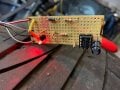
Hi Alec_t it works perfectly ") So happy! I added an red LED to make it more boy racerish
So happy! I added an red LED to make it more boy racerish
Took me ages to find anywhere that would do just a few resistors etc, In the end i remembered Tandy, and they did everything for under £5 posted!
So happy! I added an red LED to make it more boy racerish Took me ages to find anywhere that would do just a few resistors etc, In the end i remembered Tandy, and they did everything for under £5 posted!
Attachments
-
 66 KB Views: 25


