 Facebook
 Google
 GitHub
 Linkedin
Sir / Mam,
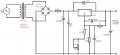
please help me to check if the attached diagram is correct even i can use for 24 hours.
i am new in electronics and i want to learn it more.
thank you.
please help me to check if the attached diagram is correct even i can use for 24 hours.
i am new in electronics and i want to learn it more.
thank you.
Attachments
-
 64.7 KB Views: 30


