Facebook
 Google
 GitHub
 Linkedin
I have been designing a circuit with a 555 timer set in a monostable capacity.
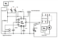
The 555 timer triggers a 5v DPDT sub mini relay, which in turn triggers a power isolated DC motor. Additionally, the circuit includes variable resistors to change the run time, as well as a reset button to stop motor function if needed. Both of these circuits are powered by separate 9v batteries.
When put together on the breadboard, the system works perfectly. However, when translated to PCB, it will only turn on and off (on when i press the trigger, and will only turn off when i press the reset, but it will stay off until the trigger is pressed again). So essentially, this giant circuit is an on/off switch.
Something is clearly wrong in my jump to PCB, but I do not know what to look for. Included are the schematics as well as the PCB layout. I have checked connections as well as polarity of items that require it.
Thank you in advance for any assistance.
View attachment Turntable Unit_pcb.pdf
View attachment Turntable Unit - Schematic_schem.pdf
Parts list;
(2) - 1k resistors
(1) - 220 resistor
(1) - 1000uf electrolytic capacitor
(1) - .01uf ceramic capacitor
(2) - 9v Batteries
(2) - Normally Open Momentary switch
(1) - 5v DPDT Sub Mini Relay
(1) - 555 timer IC
(2) - 10k sweepable resistors (103 series)
(1) - 3mm LED
(1) - DC motor
(1) - On/Off Switch
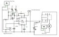
The 555 timer triggers a 5v DPDT sub mini relay, which in turn triggers a power isolated DC motor. Additionally, the circuit includes variable resistors to change the run time, as well as a reset button to stop motor function if needed. Both of these circuits are powered by separate 9v batteries.
When put together on the breadboard, the system works perfectly. However, when translated to PCB, it will only turn on and off (on when i press the trigger, and will only turn off when i press the reset, but it will stay off until the trigger is pressed again). So essentially, this giant circuit is an on/off switch.
Something is clearly wrong in my jump to PCB, but I do not know what to look for. Included are the schematics as well as the PCB layout. I have checked connections as well as polarity of items that require it.
Thank you in advance for any assistance.
View attachment Turntable Unit_pcb.pdf
View attachment Turntable Unit - Schematic_schem.pdf
Parts list;
(2) - 1k resistors
(1) - 220 resistor
(1) - 1000uf electrolytic capacitor
(1) - .01uf ceramic capacitor
(2) - 9v Batteries
(2) - Normally Open Momentary switch
(1) - 5v DPDT Sub Mini Relay
(1) - 555 timer IC
(2) - 10k sweepable resistors (103 series)
(1) - 3mm LED
(1) - DC motor
(1) - On/Off Switch