Facebook
 Google
 GitHub
 Linkedin
panic mode
- Joined Oct 10, 2011
- 5,056
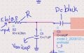
schematics is a starting point. no schematics no discussion. all electrical design starts with electrical circuit. eventually this gets translated into a mechanical representation. show us how exactly are you "tuning" your filter right now. i see no inputs or or components that can be tuned mechanically.
components have values. also diodes are polarised devices. this link explains what varactor is and how to use it in a circuit:
https://en.wikipedia.org/wiki/Varicap
note, varactor bias is a DC. also varactors need to be reverse biased or your diode will turn on and not work as a capacitor. resistor need to be high value. this need to be AC coupled to your RF circuit to avoid influence on DC bias used for tuning.
very interesting motivation but should not impact approach to problem and your workflow. good luckhelp me. I need to hand in my thesis