
I am working a MEGA-TREE project for my 2007 Christmas light display. I am using Light-O-Rama (www.lightorama.com) light controllers. I am using the 16 Channel (CTB16D) controller. I want to split the channels to allow more strings of lights than what is normally able to be connected. Instead of just having 16 strings of LED lights connected to the LOR, I would like to control 128 strings of LED lights using solid state relays. I have a very basic knowledge of building circuits and any help would be greatly appreciated...
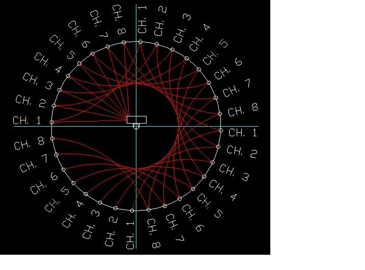
In AutoCAD, I have split the tree into four (4) quadrants with eight (8) string connection points in each. I want to connect each quadrants "CH. 1,2,3, ect..." circuits together as depicted above. When the LOR controller sends power to "CH. 1", I want it to power all four (4) quadrants "CH. 1" connection points to be switched by four (4) SSR's.

I plan to connect the neutrals to a series of SSR's also. Each quadrant will have it's own relay, and the bank of neutrals for each color of LED light strings will have its own relays per quadrant. Depending on which quadrants SSR is closed, those lights will be powered. Also depending on which colors SSR is closed, only that color will be powered in that quadrant.
EXAMPLE: I can light the red strings in the NW QUAD while lighting the green strings in the SE QUAD at the same time all the while controlling each individual string with the first eight (8) channels of the LOR controller. (I understand that each quadrant will have to do the same thing at the same time...)

I want to use the first eight (8) channels to direct the light animation for all quadrants, and use the last eight (8) channels to control the SSR's. Above, I have layed out the schematic of the enclosure in AutoCAD.

Above is the preliminary design of the SSR side of my enclosure. The eight (8) channels shown entering from the top right switch the SSR's. The first four (4) channels switch the individual quadrants and the last four (4) switches the color of LED light strings per quadrants. The SSR's are labeled according the their purpose.
A close-up of the LOR side of the enclosure for GP is located HERE.
Thank you for looking...
Rhody-
EXAMPLE: I can light the red strings in the NW QUAD while lighting the green strings in the SE QUAD at the same time all the while controlling each individual string with the first eight (8) channels of the LOR controller. (I understand that each quadrant will have to do the same thing at the same time...)
A close-up of the LOR side of the enclosure for GP is located HERE.
- Is this schematic feasible using AC current?
- Can I connect multiple strings of lights to a common neutral and use the LOR to switch the individual light strings on and off?
- Can I switch multiple SSR's with an AC current?
Thank you for looking...
Rhody-


