Using Optoisolators

Thread Starter

signalflow

Joined Mar 12, 2014
50
Hi, I am wanting to use an optoisolator to drive a relay but need some help in how to generate the 2 power supplies needed.

I have 24Vac coming in and create a 5VDC and GND1 with an LM2596 that takes up quite a bit of board space with the external components.

So how could I create a separate +Vcc and GND2 for the other side of the optoisolator.

The GND1 is generated by the bridge rectifier that is rectifying the 24Vac. So if I used say a LM7805 to create a 2nd 5V signal, I would still not have a GND2.

Thanks.
 

Thread Starter

signalflow

Joined Mar 12, 2014
50
Yes, a lot of noise is getting back into the system when switching the relay. I have tried many things and relay circuit drivers but noise still gets back in when driving the relay to switch an inductive load.
 

MaxHeadRoom

Joined Jul 18, 2013
30,808
Have you used any form of suppression/snubbers etc on relays and inductive loads?
I have performed low voltage switching of high inductive devices with no problem.
e.g. P.C. 5v TTL parallel port to VHF AC motor controller etc.
Max.
 

Thread Starter

signalflow

Joined Mar 12, 2014
50
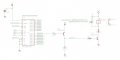
Here is the circuit I am using. I have a 120-V fan connected to the relay contacts. If I turn the fan on and off by hand with the fan switch, a lot of noise is injected back into the system. I can see it because the LCD flashes and displays wrong colors and things and sometimes freezes.

If I use the controller to turn the relay on/off, then I also get the same noise.

Any idea what I am doing wrong with my circuit?
 

Attachments

MaxHeadRoom

Joined Jul 18, 2013
30,808
A decoupling capacitor across the 5v supply is also required, 100μf - 200μf.
If that does not work, does the fan have a ground wire?
If so if may be beneficial to bond the 5v common to the same earth ground point.
Also ensure the conductors to the fan are twisted not parallel.
Max.
 

MaxHeadRoom

Joined Jul 18, 2013
30,808
Even if the fan does not have a ground wire, I would try the 5v common to earth ground.
In the case of the P.C. example I mentioned, the P.P. is connected to earth ground internally.
Max.
 

Thread Starter

signalflow

Joined Mar 12, 2014
50
OK, just tried connected Earth gnd to circuit gnd and still get noise. This is a very difficult problem to solve.

The LCD runs off of 3.3V and SPI signals. So the noise is either corrupting the 3.3V or the SPI signals.
 

ericgibbs

Joined Jan 29, 2010
21,567
hi,
From your description it sounds as though the fan motor itself is causing excessive electrical noise, its customary to suppress motor noise as close as possible to the motor.

On a side point, why do you have a 20R resistor is series with the relay, the relay is specified as 5V operating and you show a 5V supply.

I would also reduce the value of the 4.7K connected to T12 Base, to say 1K.

E
 

Thread Starter

signalflow

Joined Mar 12, 2014
50
24Vac comes in and is rectified and goes through a LM2596 simple switcher to generate 5VDC.

I am just using a honeywell house fan (120VAC) right now, but will be using the relay to control more powerful 240Vac fans and motors. Trying to get all of the noise filtered out so that the relay can drive anything.
 
Last edited:

MaxHeadRoom

Joined Jul 18, 2013
30,808
Did you make note of the comments eric made?
You could try a isolated 5v supply, say a 6v cell with two rectifiers in series, just to eliminate the supply side.
Max.
 

Thread Starter

signalflow

Joined Mar 12, 2014
50
Why do you suggest reducing 4.7K on base of T12 to 1K? To drive T12 into saturation further?

I think I had the 20 ohm resistor just because I reduced the resistor value until I was able to get the relay turned on. I suppose it limits the current that is required, but I could remove that 20-ohm resistor. Would just use more current and I am driving 6 relays.

hi,
From your description it sounds as though the fan motor itself is causing excessive electrical noise, its customary to suppress motor noise as close as possible to the motor.

On a side point, why do you have a 20R resistor is series with the relay, the relay is specified as 5V operating and you show a 5V supply.

I would also reduce the value of the 4.7K connected to T12 Base, to say 1K.

E
 

MaxHeadRoom

Joined Jul 18, 2013
30,808
Also is there any particular reason for going with negative logic for the outputs?
Otherwise I would have tended to use a single 2n7000 to drive the relay, less components with positive logic.
Max.
 

Thread Starter

signalflow

Joined Mar 12, 2014
50
I found I was able to get closer to 5V output when just using the 1st transistor (T13) as a PNP than using a NPN. The voltage gets closer to the rail with the PNP for some reason...can't remember why. That way I can use the DIGOUT signal as just a 0-5V signal with some current capability or I can use it to drive a relay.

Also is there any particular reason for going with negative logic for the outputs?
Otherwise I would have tended to use a single 2n7000 to drive the relay, less components with positive logic.
Max.
 

Thread Starter

signalflow

Joined Mar 12, 2014
50
I connected an external 5V power supply to use for the 5V of T12 and GND of T12, but it wouldn't work unless I connected the GND of the external power supply to the GND of my board. So basically I was able to isolate the 5V supply of the board from the 5V of the relay, but could not isolate the GNDs. I still get noise going when switching on the fan.
 

joeyd999

Joined Jun 6, 2011
6,456
signalflow,

You are doing something really wrong, but it's hard to tell what. Can you post some photos of your setup?

What you are trying to do has been reliably done ad infinitum. This has got to be an issue of long wires or ground loops or something like that.
 
Last edited:
Top